
Transmission charged particle microscope with an electron energy loss spectroscopy detector

a technology of electron energy loss and detector, which is applied in the direction of basic electric elements, electric discharge tubes, electrical equipment, etc., can solve the problems of reducing the spherical aberration and affecting the effect of the projecting system

Pending Publication Date: 2021-09-30
FEI CO
View PDF6 Cites 2 Cited by
  • Summary
  • Abstract
  • Description
  • Claims
  • Application Information

AI Technical Summary

Benefits of technology

The transmission charged particle microscope described in this patent has a unique projecting system that can transfer the beam of particles from the scattering plane to the EELS spectrometer, even at very high collection angles and high energy losses. The microscope has two modes: an ultra-high resolution mode and a low-HT EELS mode. By changing the excitation settings of the final projector lens, the projecting system can be optimized for different modes. This allows for better performance in both chromatic aberration and higher order aberrations. The microscope can be used to improve the accuracy and resolution of both transmission electron microscopy and scanning electron microscopy.

Problems solved by technology

Some of the electrons will undergo inelastic scattering, which means that they lose energy and maybe have their paths slightly deflected.
Other electrons may inelastically scatter on the specimen (without significant change of direction) thus experiencing a noticeable energy loss.
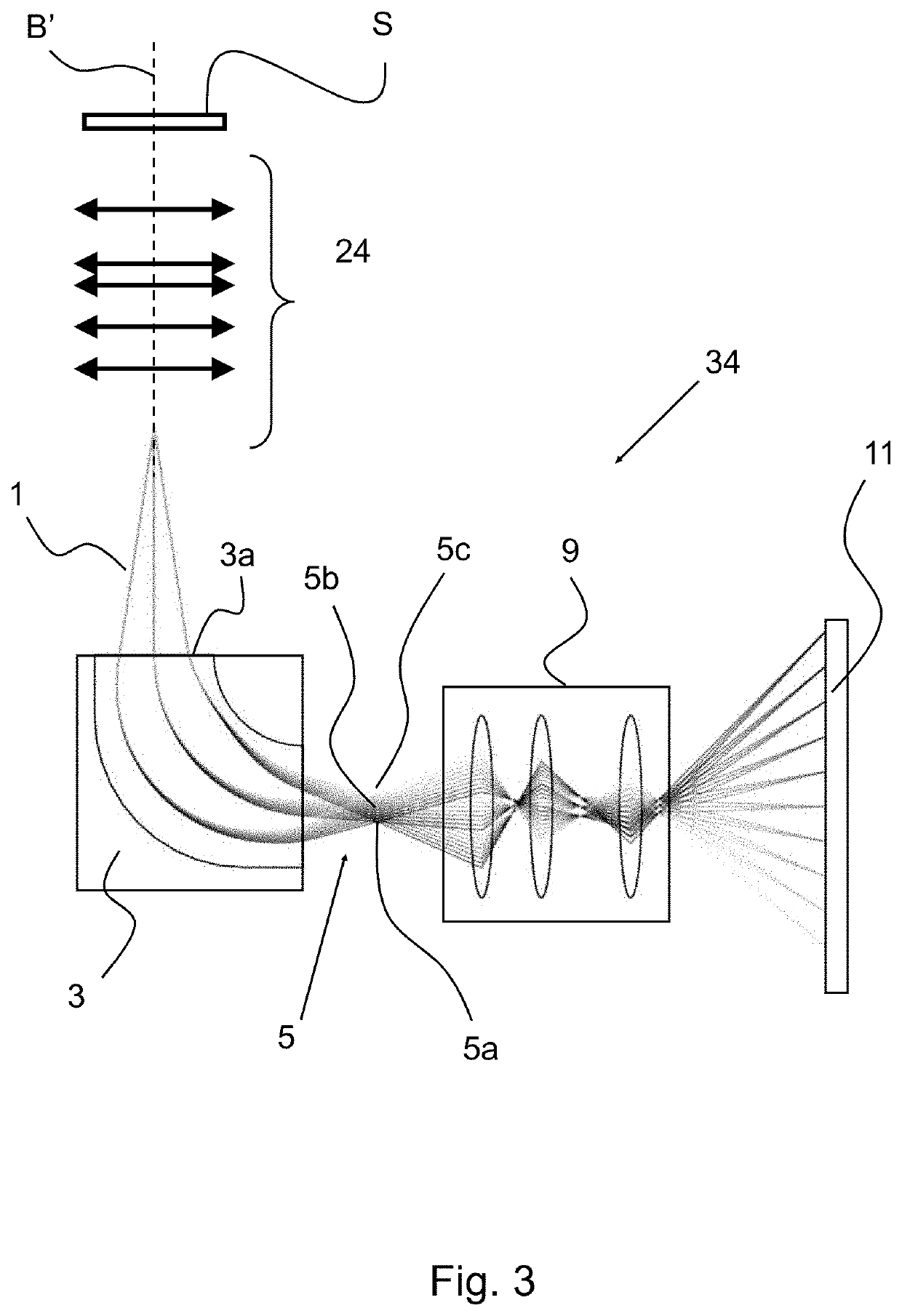
This non-traditional form of EELS leads to a larger energy loss (E) compared to the beam energy (E0) than encountered before and this poses new demands on the relative range E / E0 of electron energies that can be transferred properly by the microscope from the diffraction plane to the EELS spectrometer.
This limitation is set by the optical aberrations of the EELS spectrometer which, when the electrons travel too far off-axis (for example more than 3 mm), create blur at the EELS detector.
Such blur compromises the energy resolution of the spectrometer.
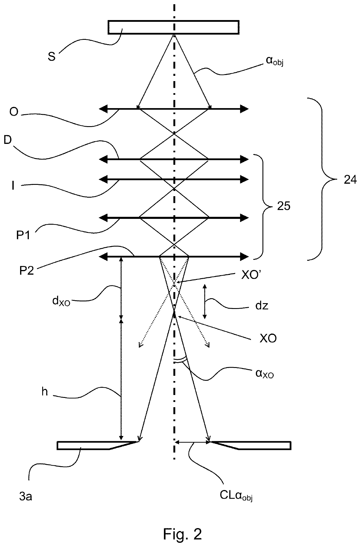
It has turned out that, especially for very large collection angle (which is equivalent to very low magnification of the TEM imaging system) the traditional optics of the imaging system of the TEM hampers the EELS performance.

Method used


Image

  • Transmission charged particle microscope with an electron energy loss spectroscopy detector
  • Transmission charged particle microscope with an electron energy loss spectroscopy detector
  • Transmission charged particle microscope with an electron energy loss spectroscopy detector

Examples


Embodiment Construction

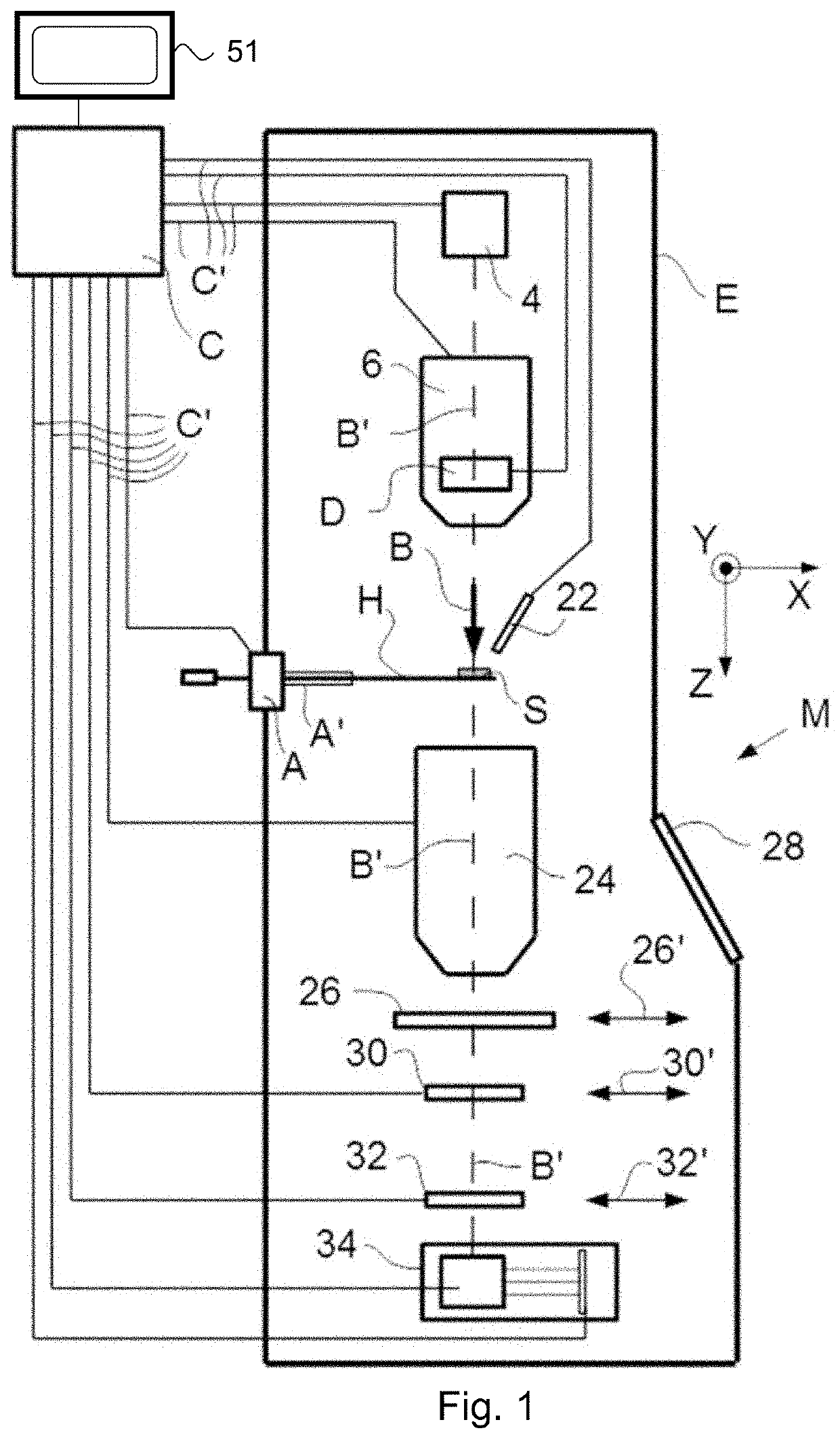
[0047]FIG. 1 is a highly schematic depiction of an embodiment of a transmission charged particle microscope M, which, in this case, is a TEM / STEM (though, in the context of the present disclosure, it could just as validly be an ion-based or proton microscope, for example). In FIG. 1, within a vacuum enclosure E, an electron source 4 (such as a Schottky emitter, for example) produces a beam (B) of electrons that traverse an electron-optical illuminator 6, serving to direct / focus them onto a chosen part of a sample S (which may, for example, be (locally) thinned / planarized). This illuminator 6 has an electron-optical axis B′, and will generally comprise a variety of electrostatic / magnetic lenses, (scan) deflector(s) D, correctors (such as stigmators), etc.; typically, it can also comprise a condenser system (the whole of item 6 is sometimes referred to as “a condenser system”).

[0048]The sample S is held on a sample holder H. As here illustrated, part of this holder H (inside enclosure...


PUM


Abstract

The invention relates to a transmission charged particle microscope comprising a charged particle beam source for emitting a charged particle beam, a sample holder for holding a sample, an illuminator for directing the charged particle beam emitted from the charged particle beam source onto the sample, and a control unit for controlling operations of the transmission charged particle microscope. As defined herein, the transmission charged particle microscope is arranged for operating in at least two modes that substantially yield a first magnification whilst keeping said diffraction pattern substantially in focus. Said at least two modes comprise a first mode having first settings of a final projector lens of a projecting system; and a second mode having second settings of said final projector lens.

Description

BACKGROUND OF THE INVENTION[0001]Charged particle microscopy is a well-known and increasingly important technique for imaging microscopic objects, particularly in the form of electron microscopy. Historically, the basic genus of electron microscope has undergone evolution into a number of well-known apparatus species, such as the Transmission Electron Microscope (TEM), Scanning Electron Microscope (SEM), and Scanning Transmission Electron Microscope (STEM), and also into various sub-species, such as a so-called “dual-beam” apparatus (e.g. a FIB-SEM) that additionally employs a Focused Ion Beam (FIB), allowing supportive activities such as ion-beam milling or Ion-Beam-Induced Deposition (IBID). The skilled person will be familiar with the different species of charged particle microscopy.[0002]Irradiation of a sample by a scanning electron beam precipitates emanation of “auxiliary” radiation from the sample, in the form of secondary electrons, backscattered electrons, X-rays and catho...

Claims


Application Information

Patent Timeline
IPC IPC(8): H01J37/28H01J37/20H01J37/26H01J37/147H01J37/10
CPCH01J37/28H01J37/20H01J37/265H01J2237/31749H01J37/10H01J2237/2802H01J2237/24485H01J37/1474H01J37/244H01J37/26H01J2237/0492
Inventor TIEMEIJER, PETER CHRISTIAAN
Owner FEI CO
Learn More