

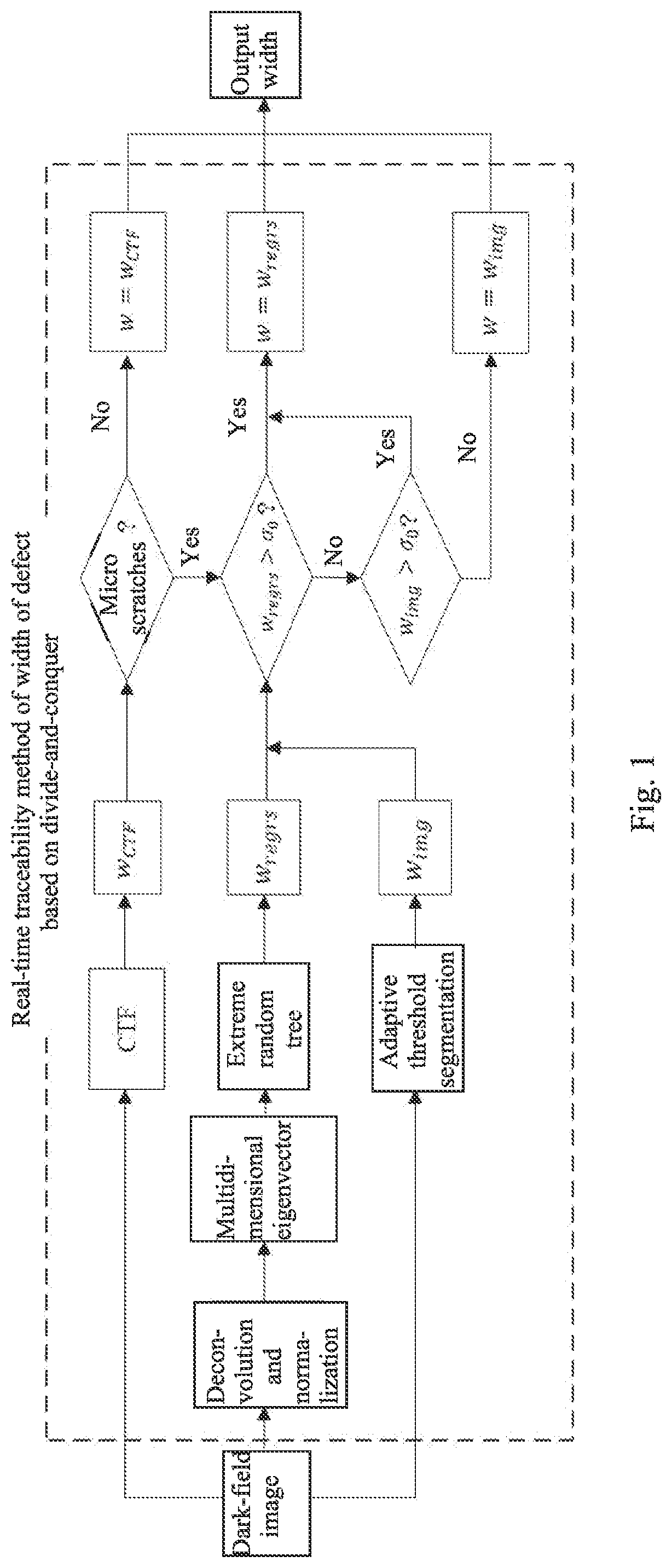
Real-time traceability method of width of defect based on divide-and-conquer
- Summary
- Abstract
- Description
- Claims
- Application Information
AI Technical Summary
Benefits of technology
Problems solved by technology
Method used
Image

Examples
first embodiment
[0110]The present invention is able to effectively trace defects whose width is close to the diffraction limit of the dark-field imaging system. Combining the regression width Wregrs and the imaging width Wimg, taking the diffraction limit of the dark-field imaging system as the boundary, the dark-field imaging system adopts white light for illumination, has the center wavelength λ of 550 nm, the numerical aperture (NA) of 0.15 for high magnification (9.7 times) detection, so that the diffraction limit of the dark-field imaging system at this time is obtained, namely,
σ=0.5λNA≈1.83μm.
The traceability method provided by the present invention is used to trace 6 defects with theoretical widths of 0.5, 1, 2, 3, 4 and 5 μm on 8 standard plates with depths of 0.028, 0.053, 0.128, 0.149, 0.205, 0.257, 0.503 and 1.155 μm, respectively, and accordingly, 6×8=48 traceability results of the width of the defect are obtained. FIGS. 5(a) and 5(b) show the results of the real-time traceability me...
second embodiment
[0111]The present invention is able to effectively trace defects in different dark-field imaging systems, as long as relevant parameters thereof are replaced. The relevant parameters are:
[0112]1) the magnification and the pixel size of the CCD, wherein the magnification and the pixel size of the CCD are used in all places where an imaging coordinate system and a pixel coordinate system need to be converted, and the magnification and the pixel size of the CCD need to be replaced during a conversion process;
[0113]2) the numerical aperture and the diffraction limit, wherein different detection systems have different numerical apertures (NAs), different diffraction limits σ0 are calculated for being replaced while using a decision model library through a formula of
σ=0.5λNA;(VIII),
[0114]here, λ is a wavelength of a light source of a corresponding dark-field detection system;
[0115]3) the point spread function, wherein different detection systems have different PSFs, which are calibrated ...
PUM
 Abstract
Description
Claims
Application Information