Particle detection via scattered light combined with incident light

Pending Publication Date: 2021-12-09
PARTICLE MEASURING SYST
View PDF10 Cites 3 Cited by
  • Summary
  • Abstract
  • Description
  • Claims
  • Application Information

AI Technical Summary

Benefits of technology

[0039]In some embodiments, the coupling between the pump beam and the incident beam may be improved by employing a narrow line width laser(s) and/or a single frequency laser(s) for the pump beam and or

Problems solved by technology

However, especially for small particles, the intensity of the unscattered light directly from the incident beam may far outweigh the

Method used


Image

  • Particle detection via scattered light combined with incident light
  • Particle detection via scattered light combined with incident light
  • Particle detection via scattered light combined with incident light

Examples


example 1

ss Pump Beam Nanoparticle Detection

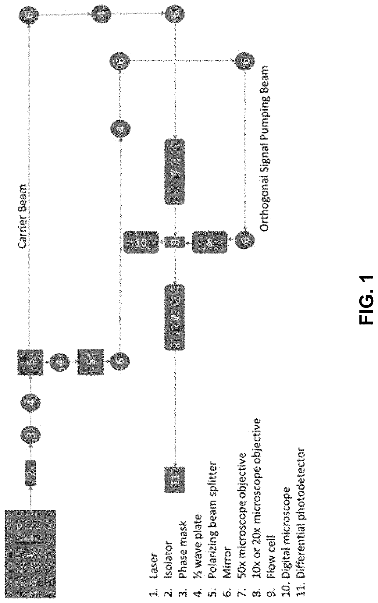
[0111]Turning now to FIG. 1, an example of a single pass pump beam particle detection system is shown. The illustrated system includes a light source 1, an isolator 2, a phase mask 3, a plurality of ½ wave plates 4, two polarizing beam splitters, a plurality of mirrors 6, a pair of microscope objectives 7, a flow cell 9, a digital microscope 10, and a photodetector 11. As can be seen, source 1 produces a beam of light which is passed through the isolator 2, then a phase mask 3 and a ½ wave plate 4. The beam is then split into an incident beam (labeled Carrier Beam) and an orthogonal signal pumping beam via polarizing beam splitter 5. The incident beam is routed through another ½ plate 4, through the first microscope objective 7 and then through the interrogation zone (flow cell 9). After passing through the flow cell 9, the incident beam is then passed through the second microscope objective 7 and finally is directed onto the photodetector. After b...

example 2

Disposed in the Opposite Direction as the Incident Beam in the Interrogation Zone

[0113]Turning now to FIG. 6, in one embodiment, the pump beam may intersect the interrogation zone in the opposite direction as the incident beam. As can be seen, a polarizing beam splitter may be used to split a beam into an incident beam and a pump beam. The incident beam may be directed via mirrors (M1, M2) through a ¼ wave plate, the flow cell, and another ¼ wave plate. The pump beam may be directed, via M3 through the same two ¼ wave plates which sandwich the flow cell, but in the opposite direction as the incident beam. Thus, the incident beam, forward scattered light from the incident beam and back-scattered light from the pump beam may all be combined and collected on the photodetector array.

example 3

Beams

[0114]Turning now to FIGS. 7-9, in one embodiment, a diffractive optical element may be used to increase the volumetric sampling rate of a particle monitoring system. FIG. 7 shows one example. As shown, the particle monitoring system includes a diffractive optical element 12 in the optical path of the incident beam. The diffractive optical element 12 functions to produce an array of beams. FIG. 8 shows a schematic diagram of the effect of the diffractive optical element on a beam of light. As the light travels from left to right, the diffractive optical element, located on the left edge of the schematic diffracts the light into, in this case, 5 beams of essentially equal intensity.

[0115]The plurality of beams is directed through a fluid flow, which contains particles. The waist of each beam is imaged onto an upper and lower pair of detector elements. FIG. 9 shows the 1-dimensional array of beams produced from the diffractive optical element. By directing the array of beams thro...


PUM


Abstract

Particle detection systems and methods are disclosed. In one embodiment, a particle detection system comprises an incident beam light source that emits an incident beam, a particle interrogation zone disposed in the path of the incident beam, a photodetector disposed to detect the incident beam after passing through the particle interrogation zone, a pump beam light source for emitting a pump beam, the pump beam being targeted at the particle interrogation zone, wherein the incident beam, the pump beam, and photodetector are arranged such that the photodetector is configured to detect a combination of light from the incident beam, scattered light due to incident beam scattering in the particle interrogation zone, and scattered light due to pump beam scattering in the particle interrogation zone.

Description

CROSS-REFERENCE TO RELATED APPLICATIONS[0001]This application claims the benefit of and priority to U.S. Provisional Patent Application No. 63 / 036,930 filed Jun. 9, 2020, and U.S. Provisional Patent Application No. 63 / 079,382 filed Sep. 16, 2020, each of which is hereby incorporated by reference in its entirety.BACKGROUND OF INVENTION[0002]Advancement of technologies requiring cleanroom conditions has resulted in the need for detection and characterization of increasingly smaller particles. For example, microelectronic foundries pursue detection of particles less than 20 nm in size, and in some cases less than 10 nm in size, as they may affect the increasingly sensitive manufacturing processes and products. Similarly, the need for aseptic processing conditions for manufacturing of pharmaceuticals and biomaterials requires accurate characterization of viable and non-viable particles to address compliance standard relating to health and human safety.[0003]Typically, these industries r...

Claims


Application Information

Patent Timeline
IPC IPC(8): G01N15/14
CPCG01N15/1434G01N2015/0046G01N2015/0053G01N15/1459G01N2015/1486G01N2015/1493G01N15/0205G01N2015/1454G01N15/0211
Inventor RODIER, DANIELMOGHADDAM, MEHRAN VAHDANIBONINO, CHRISTOPHER A.
Owner PARTICLE MEASURING SYST
Why Eureka
Try Eureka