Use of magnetic nanoparticles for the detection and quantitation of analyte(s)

Active Publication Date: 2022-01-06
QUANTUM IP HLDG PTY LTD
View PDF11 Cites 0 Cited by
  • Summary
  • Abstract
  • Description
  • Claims
  • Application Information

AI Technical Summary

Benefits of technology

[0079]In one configuration the magnetic field is generated and positioned in such a way as to maximise its effect on the magnetisable particles but minimise its effect on the

Problems solved by technology

Miniaturisation of devices can lead to slow and inefficient mixing of fluids due to an increase in viscous forces.
Many existing devices for detecting analytes attached to magnetisable particles require complex configurations that are unsuitable or are not easily adapted for miniaturisation in point-of-care testing applications.
However, the use of a very high concentration of particles has disadvantages for downstream processes in an integrated multi-step lab-on-chip assay since high particle concentrations generally increase non-specific particle-particle and particle-surface interactions, enhance field-induced particle aggregation, cause steric hindrance in particle concentration steps, obstruct chemical reactions on the particles, and sterically hinder reactions between the particles and a biosensing surface.
In such

Method used


Image

  • Use of magnetic nanoparticles for the detection and quantitation of analyte(s)
  • Use of magnetic nanoparticles for the detection and quantitation of analyte(s)

Examples


example 1

ty and Limit of Detection

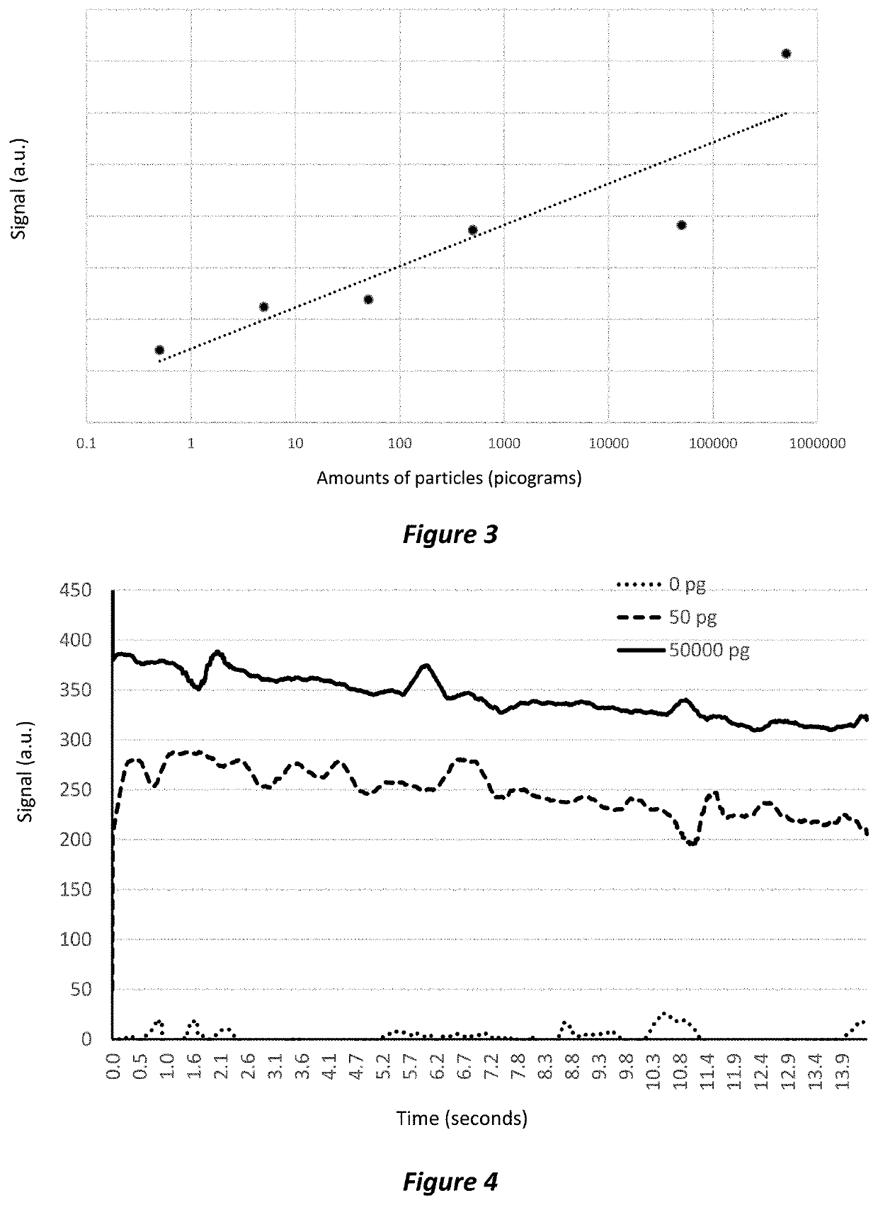
[0306]The purpose of this study was to test the sensitivity of detection.

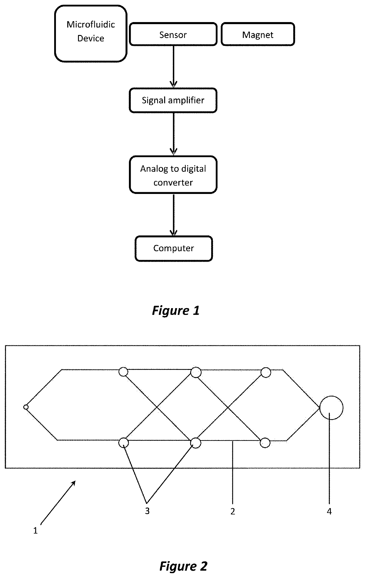
[0307]Specific amounts of magnetisable particles were added to the microfluidics system for detection. The setup of the system is summarised below.[0308]Magnetic sensor: Honeywell HMC 1021S magnetometer[0309]Magnetisable particles: Thermo Fisher Dynaparticles T1 (1 μm) Streptavidin particles[0310]Biolabel: Streptavidin[0311]Amplifier: Texas Instrument INA826[0312]Number of particles:[0313]Sample 1: control—0 pg of particles[0314]Sample 2: 0.5 pg of particles[0315]Sample 3: 5 pg of particles[0316]Sample 4: 50 pg of particles[0317]Sample 5: 500 pg of particles[0318]Sample 6: 50,000 pg of particles[0319]Sample 7: 500,000 pg of particles[0320]Acquisition of sensor data:[0321]0.012 seconds per read[0322]1,200 reads per sample[0323]approximately 15 seconds total read time

[0324]After being introduced into the microfluidics system the particles were positioned over the sensor by the microfluidi...

example 2

Detection

[0331]The purpose of this study was to test the speed of detection system.

[0332]Specific amounts of magnetisable particles were added to the microfluidics system for detection. The setup of the system is summarised below.[0333]Magnetic sensor: Honeywell HMC 1021S magnetometer[0334]Magnetisable particles: Thermo Fisher Dynaparticles T1 (1 μm) Streptavidin particles[0335]Biolabel: Streptavidin[0336]Amplifier: Texas Instrument INA826[0337]Number of particles:[0338]Sample 1: control—0 pg of particles[0339]Sample 2: 50 pg of particles[0340]Sample 3: 500,000 pg of particles[0341]Acquisition of sensor data:[0342]0.012 seconds per read[0343]1,200 reads per sample[0344]approximately 15 seconds total read time

[0345]After being introduced into the microfluidics system the particles were positioned over the sensor by the microfluidics device. The magnet was activated to bring the magnetisable particles into close proximity to the magnetic sensor. The magnet was then turned off and a pe...

example 3

of Streptavidin Protein in a Sample

[0353]The purpose of this study was to demonstrate quantitative detection of streptavidin protein in a sample as a target analyte.

[0354]Biotin conjugated to latex-particles (non-magnetisable particles) were used to capture and associate with specific amounts of streptavidin added to the microfluidics system for detection. The setup of the system is summarised below.[0355]Magnetic sensor: Honeywell HMC 1021S magnetometer[0356]Magnetisable particles: Thermo Fisher Dynaparticles T1 (1 um) Streptavidin particles[0357]Biolabel: Streptavidin[0358]Amplifier: Texas Instrument INA826[0359]Samples[0360]Sample 1: 0 pmoles / ml streptavidin protein conjugated to the magnetisable particles[0361]Sample 2: 0.33 pmoles / ml streptavidin protein conjugated to the magnetisable particles[0362]Sample 3: 3.3 pmoles / ml streptavidin protein conjugated to the magnetisable particles[0363]Sample 4: 33 pmoles / ml streptavidin protein conjugated to the magnetisable particles[0364]...


PUM


Abstract

Described is a method and device for detecting an analyte in a sample, comprising bringing a sample comprising a target analyte into contact with magnetisable particles, the particles being coated with binding molecules complementary to the target analyte, resulting in bound and unbound binder complexes, positioning the magnetisable particles, comprising both bound and unbound binder complexes, in proximity to a magnetic field sensor, changing the magnetic field sufficient to release at least a portion of the magnetisable particles, comprising both bound and unbound binder complexes, from their proximity to the magnetic field sensor, and measuring changes in a magnetic signal detected from the net movement, being either translational or rotational movement, of the magnetisable particles relative to the magnetic sensor.

Description

CROSS-REFERENCE TO RELATED APPLICATIONS[0001]This application is a continuation of international application no. PCT / AU2021 / 050497, filed May 25, 2021, which claims the benefit of and priority to Australian Application No. 2020904881, filed May 25, 2020, both of which are expressly incorporated herein by reference.FIELD OF THE INVENTION[0002]The invention relates to a method for detecting an analyte(s) in a sample, and more specifically, the use of magnetisable nanoparticles and a magnetic sensor system. The invention also relates to a device for detecting analytes based on the use of magnetisable nanoparticles.BACKGROUND OF THE INVENTION[0003]There are many known methods to detect and quantify analytes in a sample. Such systems require an indirect method to quantify the analyte by detecting and measuring a complex that is bound to the analyte. Typically, such methods rely on a binding or recognition system whereby a visualisation aid is coated or linked to a binding molecule that b...

Claims


Application Information

Patent Timeline
IPC IPC(8): G01N33/543
CPCG01N33/54326G01N33/53G01N2333/535G01N2333/5412G01N2333/765G01N33/54333G01N2333/525G01N33/547G01N2333/4737B01L3/5027B82Y5/00G01N27/745B01L2400/043B01L3/50273G01R33/1269G01N33/54313G01N33/553
Inventor KING, PAUL JEREMYLO, CAMDEN YEUNG-WAH
Owner QUANTUM IP HLDG PTY LTD
Why Eureka
Try Eureka