
Operating method of etching device

a technology of etching device and operation method, which is applied in the direction of photomechanical equipment, instruments, cleaning of hollow objects, etc., can solve the problems of difficult removal of negatively charged by-products, large amount of particles generated by the etching process, and inability to easily remove negatively charged by-products, etc., and achieve the effect of improving the performance of the wafer

Pending Publication Date: 2022-03-31
NAN YA TECH
View PDF3 Cites 0 Cited by
  • Summary
  • Abstract
  • Description
  • Claims
  • Application Information

AI Technical Summary

Benefits of technology

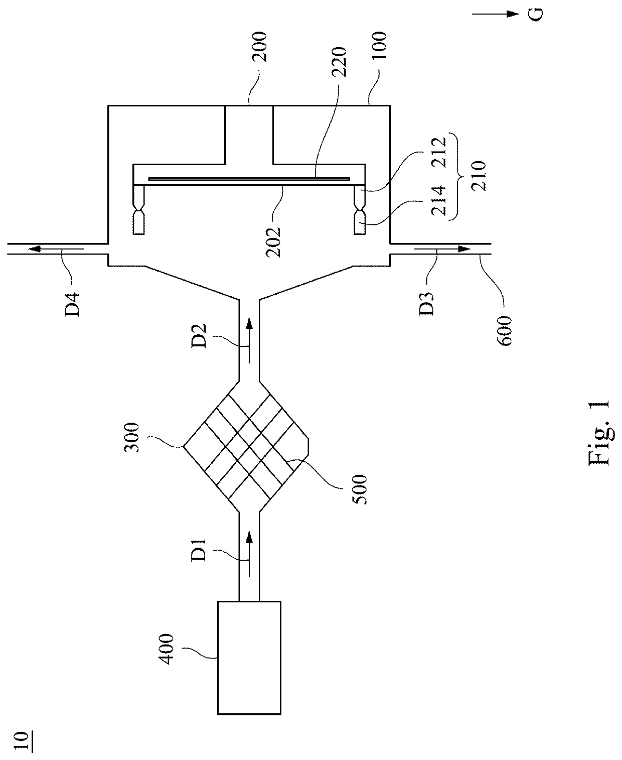
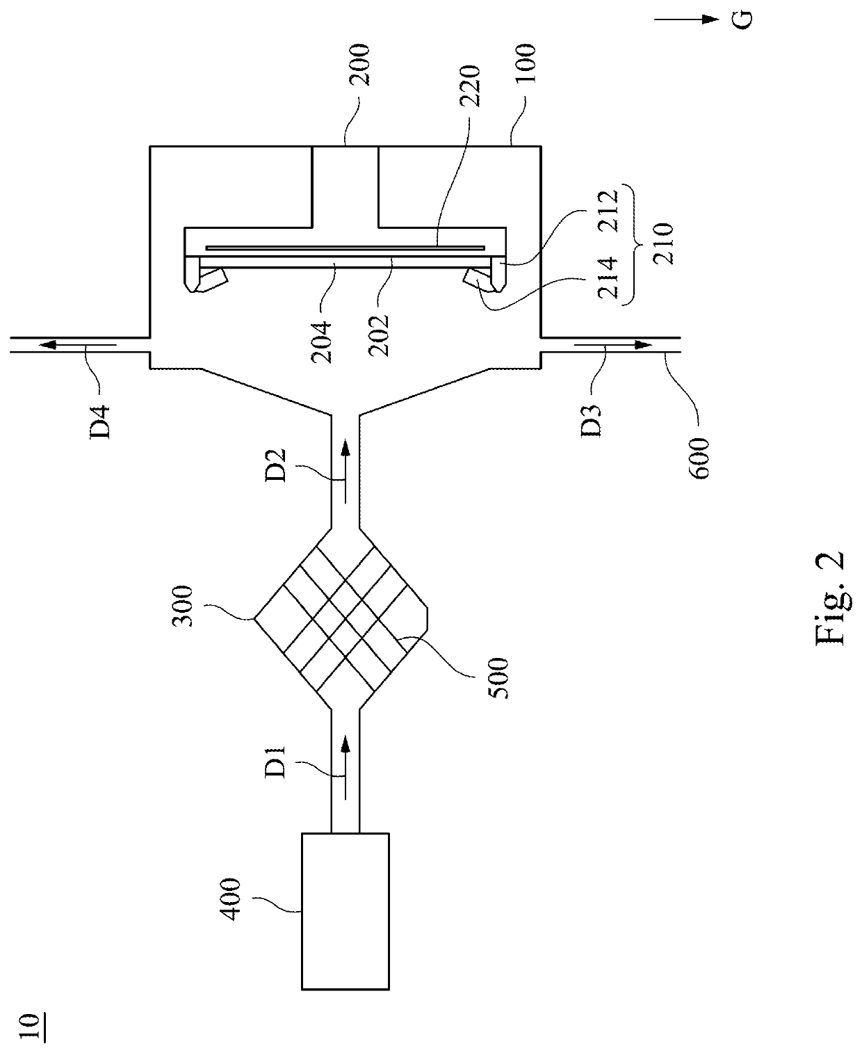
[0010]In summary, the disclosure provides a method for performing an etching process. The wafer is disposed on the wafer-mounting surface of the wafer holder, and the wafer-mounting surface of the wafer holder is in parallel with a gravity direction, and thus particles may drop on a side surface of the wafer without dropping on a top surface of the wafer. Therefore, the contamination problem on the top surface of the wafer can be resolved, and performance of the wafer can be improved.

Problems solved by technology

However, the plasma etching process often generates a large amount of particles, such as negatively charged by-products generated by chemical mechanisms and attached with electrons due to exposure to the plasma.
As a result of the interaction between the magnetic field and the electric field in a chamber, the negatively charged by-products are suspended above the wafer and are not easily to be removed.
Therefore, after the plasma etching process is performed, the suspended negatively charged by-products (particles) drop on the top surface of the wafer, thus causing contamination.

Method used


Image

  • Operating method of etching device
  • Operating method of etching device
  • Operating method of etching device

Examples


Embodiment Construction

[0018]Reference will now be made in detail to the present embodiments of the disclosure, examples of which are illustrated in the accompanying drawings. Wherever possible, the same reference numbers are used in the drawings and the description to refer to the same or like parts.

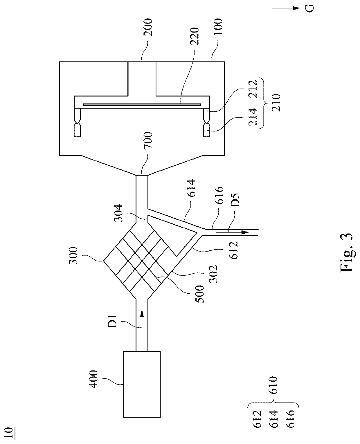
[0019]FIG. 1 is a schematic view of an etching device 10 at one operation state accordance with one embodiment of the present disclosure, while FIG. 2 is a schematic view of the etching device 10 at another operation state in accordance with one embodiment of the present disclosure. Referring to FIG. 1, the etching device 10 includes a chamber 100, a wafer holder 200, a vacuum sealing device 300, a gas source 400, and an inductive coil 500. The wafer holder 200 is disposed in the chamber 100. The wafer holder 200 has a wafer-mounting surface 202 in parallel with a gravity direction G.

[0020]The vacuum sealing device 300 is connected between the chamber 100 and the gas source 400. As shown in FIG. 1, the gas so...


PUM

PropertyMeasurementUnit
acute angleaaaaaaaaaa
gravityaaaaaaaaaa
magnetic fieldaaaaaaaaaa

Abstract

A method includes the following steps. A wafer is disposed on a wafer-mounting surface of a wafer holder that is disposed in a chamber. The wafer-mounting surface is in parallel with a gravity direction. A gas is flown from a gas source to vacuum sealing device. An inductive coil wrapping around a vacuum sealing device excites the gas into plasma. The plasma is injected to the wafer.

Description

CROSS-REFERENCE TO RELATED APPLICATION[0001]This application is a Divisional application of the U.S. application Ser. No. 16 / 247,539, filed on Jan. 14, 2019, which claims priority of U.S. Provisional Application Ser. No. 62 / 775,370, filed on Dec. 4, 2018, the entirety of which is incorporated by reference herein in their entireties.BACKGROUNDTechnical Field[0002]The present disclosure relates to an operation method of an etching device. More particularly, the present disclosure relates to an operation method of an etching device that is used to perform a dry etching process, such as photoresist stripping.Description of Related Art[0003]In current semiconductor industry, a dry etching process is generally used to perform photoresist stripping. Moreover, while an operation of transferring a photoresist pattern is performed, the dry (plasma) etching process has an advantage of high accuracy, and thus the plasma etching process is used for processing a large amount of wafers on semicond...

Claims


Application Information

Patent Timeline
Patent Type & Authority Applications(United States)
IPC IPC(8): H01J37/32H01L21/67H01L21/02H01L21/311H01L21/027B08B5/02B08B9/032G03F7/20
CPCH01J37/32862H01L21/67069H01L21/0206H01L21/31138H01L21/0273H01J37/3244H01J37/3211B08B5/02B08B9/0328G03F7/70933H01J37/32834H01J2237/334H01J37/32724H01L21/3065H01L21/6719H01L21/67017B08B5/04B08B15/00B08B9/035
Inventor TSAI, FENG-JUDOONG, SHYUE-RU
Owner NAN YA TECH
Learn More