
Transcervical access systems for intrauterine fluid exchange, such as placement of hydrogels formed in situ

a technology of intrauterine fluid exchange and access system, which is applied in the direction of catheter, application, infusion syringe, etc., can solve the problems of high rate of adhesion re-formation, pain and debilitating medical problems, and failure of medical intervention

Pending Publication Date: 2022-05-12
PRAMAND LLC
View PDF0 Cites 0 Cited by
  • Summary
  • Abstract
  • Description
  • Claims
  • Application Information

AI Technical Summary

Benefits of technology

This patent describes methods and devices for delivering and removing fluids with respect to the uterine cavity. The invention involves introducing a flowable material into the uterine cavity to prevent adhesion between damaged tissues after surgery or to provide mechanical support for uterine tissues. The methods and devices can also be used for delivering other fluids for therapeutic or diagnostic purposes. The invention provides a way to prevent adhesion in the uterine cavity and to provide a tamponade to stop bleeding after surgery. The hydrogel compositions used in the invention can be crosslinked in vivo to form a stable gel that does not apply pressure on the patient. The hydrogel can be delivered through a catheter system and can be used as a tamponade to prevent adhesion or bleeding. The invention also includes a hydrogel applicator that allows for simultaneous deployment of two solutions and a static mixer for more rapid mixing of the solutions.

Problems solved by technology

This complication can lead to painful and debilitating medical problems, including but not limited to postoperative adverse events, failure of the medical intervention, and infertility.
Surgical dissection and resection of adhesions often result in a high rate of adhesion re-formation.
Current methods for preventing adhesions, including but not limited to, intrauterine adhesions, have limited effectiveness.

Method used


Image

  • Transcervical access systems for intrauterine fluid exchange, such as placement of hydrogels formed in situ
  • Transcervical access systems for intrauterine fluid exchange, such as placement of hydrogels formed in situ
  • Transcervical access systems for intrauterine fluid exchange, such as placement of hydrogels formed in situ

Examples


example 1

Studies

[0168]This example illustrates the efficacy of a transcervical access system via a benchtop study with a uterine model.

[0169]In this example, a benchtop uterine model with a clam-shell design was used. The uterine model consisted of a uterine cavity shaped mold in each side of a plastic clam-shell case. When closed, the model had a circular opening and a tubular space at one end, which simulated the cervix, and an internal triangular space which simulated the body cavity of the uterine cavity.

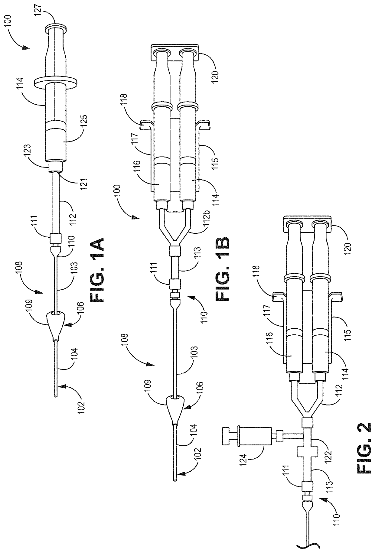
[0170]In this example, the closed uterine model was prefilled with saline using a syringe or a catheter to simulate residual fluids in the uterine cavity that may be present after a transcervical hysteroscopic procedure. The experimental design allowed for testing the efficacy of the transcervical access system with respect to dilution resistance. A transcervical access system was assembled similar to the image in FIG. 1B. A set of first solutions were prepared as a mixture of an electro...

example 2

i-hysterectomy Comparative Study

[0175]This comparative example illustrates the use of an existing transcervical catheter to delivery hydrogel into a human uterus.

[0176]Six human patients were part of this study. For each patient, a modified Cook® Goldstein Sonohysterography Catheter was used. The Cook Goldstein Sonohysterography Catheter has a movable acorn-shaped positioner that can be positioned along the catheter, with ink bands located on the catheter as reference marks. The catheter was connected via a luer lock to a dual syringe assembly as described below. In this study, the Cook Goldstein Sonohysterography Catheter was modified by cutting off the catheter at a location proximal to both the round closed tip and the oval sideport. As modified, the catheter had an open port at the distal tip.

[0177]For the study, six female patients were chosen. Patient selection was based first on a determination that a hysterectomy was medically needed for the patient and second on the willing...

example 3

terus Benchtop Study

[0182]This example illustrates the efficacy of a transcervical access system to deliver hydrogel to a human uterus via an ex-vivo uterus benchtop study.

[0183]In this example, an excised human uterus was obtained according to standard medical research protocols. The weight of the ex-vivo uterus was 101 grams.

[0184]A transcervical access system similar to the image in FIG. 1B was used. Each syringe had a volume of 10 ml. A set of first solutions were prepared as a mixture of an electrophilic precursor and a nucleophilic precursor, with a 1:1 ratio of reactive ester end groups to reactive amine end groups for each formulation. A 5 ml aliquot of the first solution in 20 mM monobasic buffer solution, pH 4 was drawn into a first syringe. Into a second syringe, 5 ml of a pH 9.9 sodium borate / sodium phosphate dibasic accelerator solution was drawn. In each case, the first solutions were colored with a dilute concentration of FD&C blue #1. The second solutions were uncolo...


PUM

PropertyMeasurementUnit
Lengthaaaaaaaaaa
Lengthaaaaaaaaaa
Lengthaaaaaaaaaa

Abstract

Transcervical access systems for providing transcervical movement of fluids are described. The transcervical access systems are effective for transferring a broad range of fluids, including the delivery of hydrogel precursors, saline, and imaging fluids, to the uterine cavity. The transcervical access systems are also effective for removing fluids from the uterine cavity, such as residual bodily fluids, residual fluids from a procedure, or tissue. The transcervical access systems described include flow limiters, such as egress limiters and / or cervical plugs. Methods of use of the transcervical access systems are also described. Methods include using the transcervical access systems to transcervical access the uterine cavity and install hydrogel. The transcervical access systems and associated methods can be useful for providing degradable hydrogel in the uterine cavity, including the cervical canal, for the prevention of adhesions following intrauterine procedures.

Description

CROSS REFERENCE TO RELATED APPLICATIONS[0001]This application claims priority to copending U.S. provisional patent application 63 / 113,013 filed on Nov. 12, 2020 to Bassett et al., entitled “Placement of Hydrogels Formed In Situ, Composition Design and Delivery Tools for Intrauterine Use,” incorporated herein by reference.FIELD OF USE[0002]Aspects of the invention relate to methods of applying materials delivered to the uterine cavity, including in situ forming hydrogels, and to tools useful for the placement, instrumentation, and delivery of these materials.BACKGROUND[0003]The unwanted adherence of scar tissue that can occur following intrauterine procedures, known as intrauterine adhesions typically occurs when two injured tissue surfaces are close to one another. This complication can lead to painful and debilitating medical problems, including but not limited to postoperative adverse events, failure of the medical intervention, and infertility. Surgical dissection and resection o...

Claims


Application Information

Patent Timeline
IPC IPC(8): A61B17/12A61M25/00A61M5/19A61M5/315A61B17/42
CPCA61B17/12181A61M25/0082A61B17/12099A61M2210/1433A61M5/31596A61B17/42A61M5/19A61M5/3291A61B2017/4216A61B2017/00004A61B2017/00942A61B2017/00898A61B2090/3966A61B2090/036A61B2017/00557A61B2017/00893A61B17/1204A61B17/12186A61M31/00A61B2090/373A61B2090/3925A61L2300/404A61L2300/41A61L2300/43A61L2300/442A61L2400/06A61L31/145A61L31/16A61L31/148A61L31/06C08L71/02A61M25/007
Inventor BASSETT, MICHAELFELDBERG, IAN
Owner PRAMAND LLC
Learn More