
Multi-photon microscopy, imaging method using time-gated detection thereof

a multi-photon microscope and time-gated detection technology, applied in the field of multi-photon microscopes, can solve the problems of long image acquisition time and limitation of conventional multi-photon microscopes using pulsed lasers with high repetition rates, and achieve the effects of improving imaging performance, increasing peak power, and improving snr

Pending Publication Date: 2022-05-12
KOREA ADVANCED INST OF SCI & TECH
View PDF4 Cites 2 Cited by
  • Summary
  • Abstract
  • Description
  • Claims
  • Application Information

AI Technical Summary

Benefits of technology

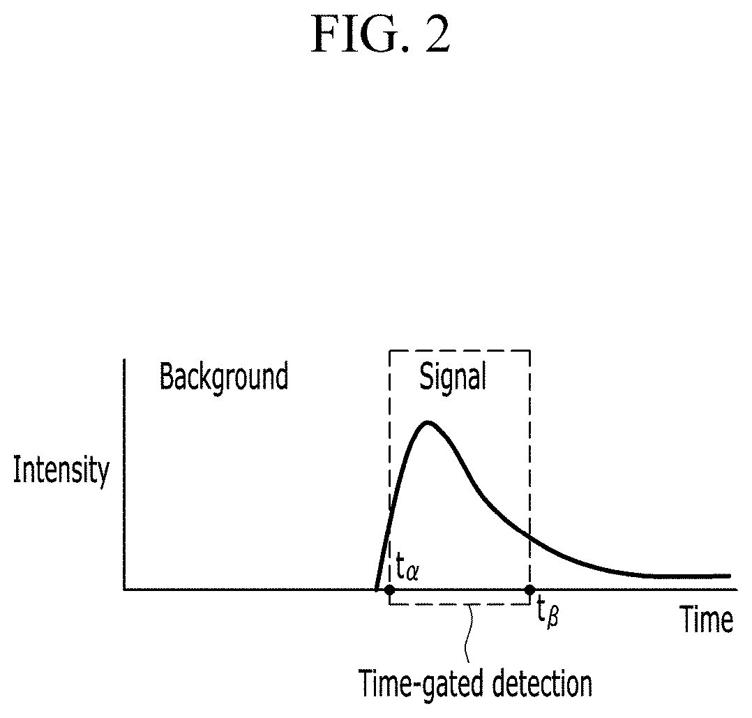
This patent is about improving the performance of imaging techniques by adjusting the repetition rate of a pulsed laser and the timing of detection. This can increase peak power and improve signal-to-noise ratios, resulting in better image quality. Additionally, reducing the average power of the laser can lower sample damage. The patent also mentions using time-gated detection to remove background signals and improve signal-to-noise ratios.

Problems solved by technology

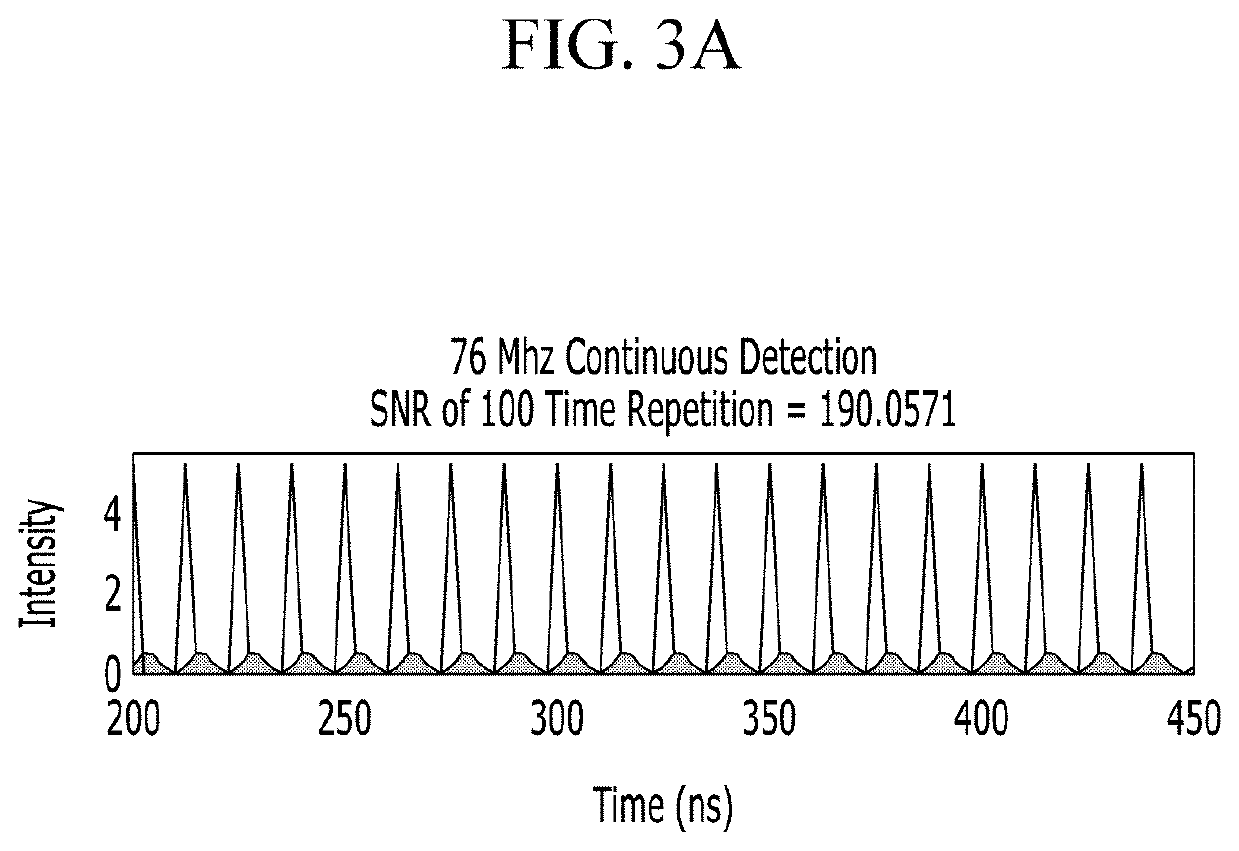
Thus, a conventional multi-photon microscope using a pulsed laser with a high repetition rate (e.g., 76-100 MHz) has a limitation on the peak power.
However, since the conventional multi-photon microscope requires a technique (e.g., frame averaging) to increase a signal to noise ratio (SNR), it has a drawback in that the image acquisition time is lengthened.

Method used


Image

  • Multi-photon microscopy, imaging method using time-gated detection thereof
  • Multi-photon microscopy, imaging method using time-gated detection thereof
  • Multi-photon microscopy, imaging method using time-gated detection thereof

Examples


Embodiment Construction

[0029]Hereinafter, embodiments of the present invention will be described in detail with reference to the attached drawings so that the person of ordinary skill in the art may easily implement the present invention. However, the present invention may be modified in various ways and is not limited to the embodiments described herein. In the drawings, elements irrelevant to the description of the present invention are omitted for simplicity of explanation, and like reference numerals designate like elements throughout the specification.

[0030]In the description, when a part is referred to “include” a certain element, it means that it may further include other elements rather than exclude other elements, unless specifically indicates otherwise. In the description, the terms such as “ . . . unit”, “ . . . er / or”, “ . . . module”, and the like refer to units that process at least one function or operation, which may be implemented with a hardware, a software or a combination thereof.

[0031...


PUM

PropertyMeasurementUnit
fluorescentaaaaaaaaaa
fluorescenceaaaaaaaaaa
currentaaaaaaaaaa

Abstract

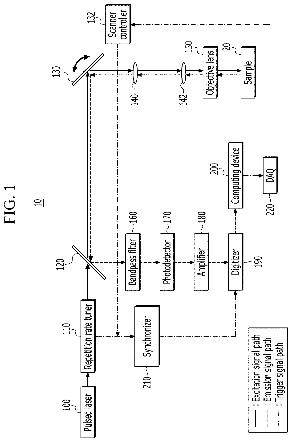
The multi-photon microscope comprises a repetition rate tuner that lowers an optical pulse train emitted from a pulsed laser to a repetition rate for time-gated detection, a scanner that scans the optical pulse train transmitted from the repetition rate tuner in x-axis and y-axis directions, an objective lens that irradiates an optical signal scanned by the scanner to the sample and acquires a fluorescence signal emitted from the excited fluorescent material, a photodetector that photoelectrically converts the fluorescence signal acquired by the objective lens, an amplifier that converts a current signal output from the photodetector into a voltage signal, a digitizer that samples the voltage signal output from the amplifier, and a computing device that separates sampling data output from the digitizer with a detection window set in time domain, and generates an image based on the sampling data separated by the detection window.

Description

CROSS-REFERENCE TO RELATED APPLICATION[0001]This application claims priority to and the benefit of Korean Patent Application No. 10-2020-0046708 filed in the Korean Intellectual Property Office on Apr. 17, 2020, and PCT / KR2021 / 001434 filed on Feb. 3, 2021, the entire contents of which are incorporated herein by reference.BACKGROUND(a) Field[0002]The present invention relates to a multi-photon microscope.(b) Description of the Related Art[0003]A multi-photon microscope excites a fluorescent material using multi-photon excitation. Here, the multi-photon microscope excites an energy level of a ground state to an intermediate energy level with a photon having a low energy, and then excites the intermediate energy level to a final energy level with a next photon. Then, the multi-photon microscope acquires a light emitted from the excited fluorescent material and performs imaging using the acquired light. This multi-photon microscope has the merit of enabling deep tissue imaging with high...

Claims


Application Information

Patent Timeline
Patent Type & Authority Applications(United States)
IPC IPC(8): G01N21/64G02B21/04G02B21/16G02B21/00
CPCG01N21/6458G01N21/6428G02B21/002G02B21/16G02B21/04G02B21/0076G02B21/0064G02B21/008G02B21/0084
Inventor YOO, HONGKIKIM, WOOSEOPKANG, JUEHYUNGKANG, UNGYO
Owner KOREA ADVANCED INST OF SCI & TECH
Learn More