
Device for detecting contamination with photosynthesis inhibitor and method for detecting contamination with photosynthesis inhibitor

a technology of photosynthesis inhibitor and device, which is applied in the direction of fluorescence/phosphorescence, instruments, withdrawing sample devices, etc., can solve the problems of sudden inhibition of photosynthesis in surface seawater in the periphery of the plant, difficult real-time measurement, and equipment not suitable for water quality monitoring equipment in offshore plants. , to achieve the effect of simple method and low cos

Pending Publication Date: 2022-05-26
NAT INST FOR ENVIRONMENTAL STUDIES +1
View PDF0 Cites 0 Cited by
  • Summary
  • Abstract
  • Description
  • Claims
  • Application Information

AI Technical Summary

Benefits of technology

The invention provides a small and affordable device for detecting contamination with a photosynthesis inhibitor that can measure the fluorescence quantum efficiency of phytoplankton in real-time. This device can also determine if there is sudden contamination with heavy metals in the test liquid. Additionally, a simple method is provided for detecting contamination with a photosynthesis inhibitor.

Problems solved by technology

As a result of examination conducted on chemical analysis methods that can be performed in offshore plants, the inventors clarified that many chemical analysis methods require time-consuming pretreatments such as a desalting operation to quantify heavy metals in seawater, and thus real-time measurement is not easy.
Further, it is considered that since simultaneous analysis of multiple elements requires expensive and large-scale equipment such as inductively coupled plasma-mass spectrometers and inductively coupled plasma spectrophotometers, such equipment is not suitable as water quality-monitoring equipment in offshore plants.
It is considered that the occurrence of leakage of heavy metals from offshore plants is accidental and contamination with heavy metals at a concentration that causes photosynthesis inhibition in surface seawater in the periphery of the plant is sudden.

Method used


Image

  • Device for detecting contamination with photosynthesis inhibitor and method for detecting contamination with photosynthesis inhibitor
  • Device for detecting contamination with photosynthesis inhibitor and method for detecting contamination with photosynthesis inhibitor
  • Device for detecting contamination with photosynthesis inhibitor and method for detecting contamination with photosynthesis inhibitor

Examples


experimental example 1

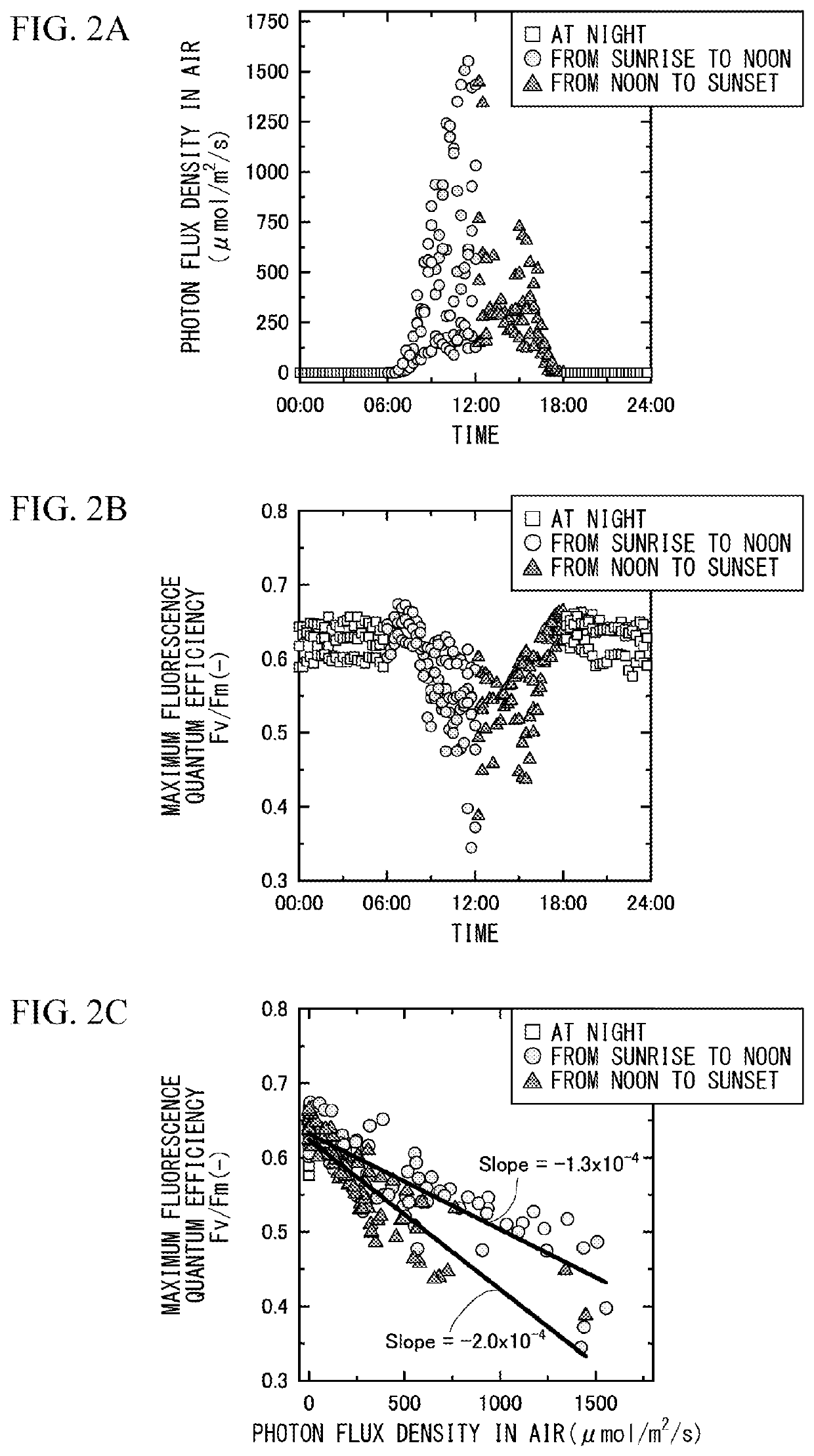
[0161](Natural Fluctuation in Maximum Fluorescence Quantum Efficiency)

[0162]The influence of light, applied to phytoplankton during collection, on the maximum fluorescence quantum efficiency of the phytoplankton was analyzed. The analysis was continuously carried out on the Japan Agency for Marine-Earth Science and Technology research vessel Kaimei (voyage number KM17-12C) in the Okinawa Trough sea area for 98 hours.

[0163]The fluorescence quantum efficiency of a plant is a parameter for estimating the electron transfer rate of Photosystem II in a photosynthetic reaction. By holding a plant in a dark place, plastoquinone in the photosystem is completely oxidized. The fluorescence quantum efficiency here is referred to as the maximum fluorescence quantum efficiency.

[0164]First, the aerial photon flux densities acquired at 1-minute intervals were averaged every 15 minutes, and the diurnal fluctuation was analyzed. FIG. 2A is a graph showing the distribution of the aerial photon flux de...

experimental example 2

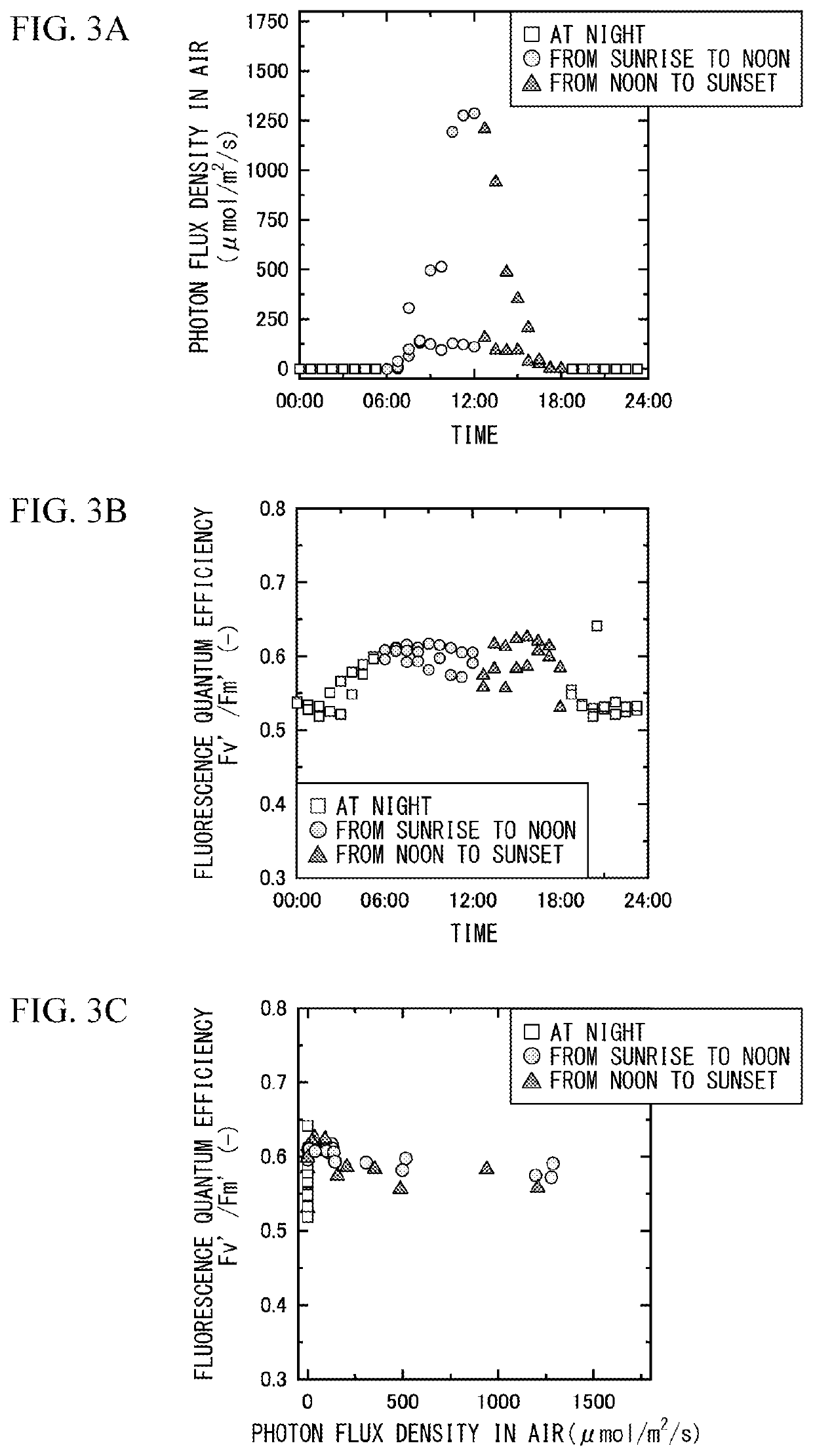
[0176](Removal of Diurnal Fluctuation in Fluorescence Quantum Efficiency)

[0177]A method of alleviating the diurnal fluctuation in the fluorescence quantum efficiency by irradiating the seawater with weak light in advance was examined. The analysis was performed in the Okinawa Trough sea area as in Experimental Example 1, and the experimental period was set to 61 hours continuously.

[0178]Surface water was collected in each of three light-blocking containers at a constant speed for 30 minutes. A phase difference of 30 minutes was provided for the time of starting the collection in each container. Each of the collected seawater was retained in each container and intermittently discharged from each container for 30 minutes.

[0179]The seawater in the light-blocking container was continuously irradiated with a white LED having a photosynthetic effective wavelength range (400 to 700 nm) at an intensity of 150 μmol / m2 / s. The fluorescence quantum efficiency of intermittently discharged seawat...

experimental example 3

[0185](Detection 1 of Heavy Metal based on Fluorescence Quantum Efficiency Fv′ / Fm′)

[0186]A method of detecting the presence of a heavy metal in seawater was examined based on the measured value of the fluorescence quantum efficiency.

[0187]Similar to Experimental Examples 1 and 2, surface water in the Okinawa Trough sea area was collected in one pretreatment tank. The pretreatment tank was continuously irradiated with light having an underwater photon flux density of (150 μmol / m2 / s) using a white LED having a photosynthetic effective wavelength range (400 to 700 nm).

[0188]After the irradiation with light for approximately 60 minutes, a sea-floor mineral simulated eluate containing zinc and lead was added to the seawater in the pretreatment tank in the combination of any of the concentrations listed in Table 1. The fluorescence quantum efficiency Fv′ / Fm′ of seawater in the pretreatment tank was measured from the start of irradiation with light to 180 minutes after the addition of the ...


PUM

PropertyMeasurementUnit
concentrationaaaaaaaaaa
photosynthetic effective wavelength rangeaaaaaaaaaa
wavelength rangeaaaaaaaaaa

Abstract

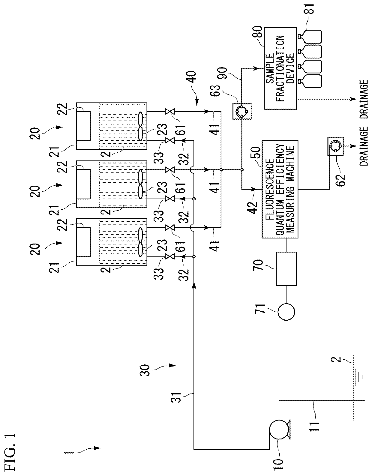
The present invention provides a device (1) for detecting contamination with a photosynthesis inhibitor, the device including a collection device (10) configured to collect a test liquid, a light-blocking pretreatment tank (21) configured to store the test liquid (2) collected by the collection device in a state of containing phytoplankton, a stirring device configured to maintain a floating state of the phytoplankton in the test liquid stored in the pretreatment tank, an irradiation light source configured to irradiate the phytoplankton in the test liquid stored in the pretreatment tank with weak light having an underwater photon flux density that does not cause photoinhibition, a drainage conduit (40) configured to allow the test liquid discharged from the pretreatment tank to flow thereinto, and a fluorescence quantum efficiency measuring machine (50) provided for the drainage conduit and configured to measure a fluorescence quantum efficiency of the phytoplankton in the test liquid discharged from the pretreatment tank, and a method for detecting contamination with a photosynthesis inhibitor, the method including a liquid supply step, a storing and weak-light irradiation step, and a fluorescence quantum efficiency measurement step.

Description

TECHNICAL FIELD[0001]The present invention relates to a device for detecting contamination with a photosynthesis inhibitor and a method for detecting contamination with a photosynthesis inhibitor. Priority is claimed on Japanese Patent Application No. 2019-026026, filed Feb. 15, 2019, the content of which is incorporated herein by reference.BACKGROUND ART[0002]In recent years, sea-floor mineral resources for commercialization have been developed all over the world. As a result of tests conducted in research vessels (Kairei, Chikyu, and Kaimei) and laboratories, the inventors found that the reactivity between sulfide minerals of sea-floor hydrothermal deposits and seawater increases under high-temperature and oxidative conditions such as the ocean surface layer, various heavy metal elements are eluted, and the eluate containing heavy metal elements at a ppb to ppm level leads to a decrease in the current existing amount of phytoplankton and growth inhibition.[0003]Based on this findi...

Claims


Application Information

Patent Timeline
Patent Type & Authority Applications(United States)
IPC IPC(8): G01N21/64
CPCG01N21/6486G01N21/94G01N2021/635G01N2001/1025C02F2103/007C02F2103/08G01N1/14G01N2035/00534G01N35/1095
Inventor KOSHIKAWA, HIROSHIKAWACHI, MASANOBUFUCHIDA, SHIGESHIOTA, SHUHEIMIWA, TETSUYAFURUSHIMA, YASUOKONDO, SHUNSUKE
Owner NAT INST FOR ENVIRONMENTAL STUDIES
Learn More