Vapor deposition device

a technology of vapor deposition and vaporization, which is applied in the direction of vacuum evaporation coating, coating, sputtering coating, etc., can solve the problems of impaling durability, achieve uniform coating thickness, improve mass productivity, and reduce the effect of coating thickness variation

Pending Publication Date: 2022-07-21
THERMALYTICA INC
View PDF0 Cites 0 Cited by
  • Summary
  • Abstract
  • Description
  • Claims
  • Application Information

AI Technical Summary

Benefits of technology

[0016]The effect to be obtained by the above aspect will be briefly described.
[0017]That is, it is possible to provide vapor deposition device suitable for mass production with little variations in coating thickness on multiple substrates even if ceramic vapor deposition is to be conducted on multiple substrates by electron beam. According to the above aspect, electron-beam vapor deposition can be adopted since vapor deposition can be conducted with the substrate placed above the ceramic evaporation source. In addition, since the multiple substrates are rotated and revolved while being held by the left and right substrate support plates, coating thickness can be easily controlled to be uniform. Further, since the left and right sides can be changed in the loading chamber, the substrates as vapor deposition targets can be changed without devacuumization, which improves mass productivity.

Problems solved by technology

However, due to a difference in thermal expansion coefficient between the metal of the substrates and the coated ceramic caused by heat cycle applied to the substrates, the coating may crack or spall resulting in impairing durability.

Method used


Image

  • Vapor deposition device
  • Vapor deposition device
  • Vapor deposition device

Examples


embodiment

1. Outline of Embodiment

[0039]First, an outline of a typical embodiment disclosed herein will be described. Reference signs used in the drawings and referred to in parentheses in the outline of the typical embodiment merely exemplify those included in the concept of the components to which the reference signs are given. The branch numbers of the reference signs (e.g., hyphened numbers, “L” and “R”) are given for the distinction of multiple same structures. If such distinction is unnecessary, reference signs without branch numbers are used as general numbers.

[1]

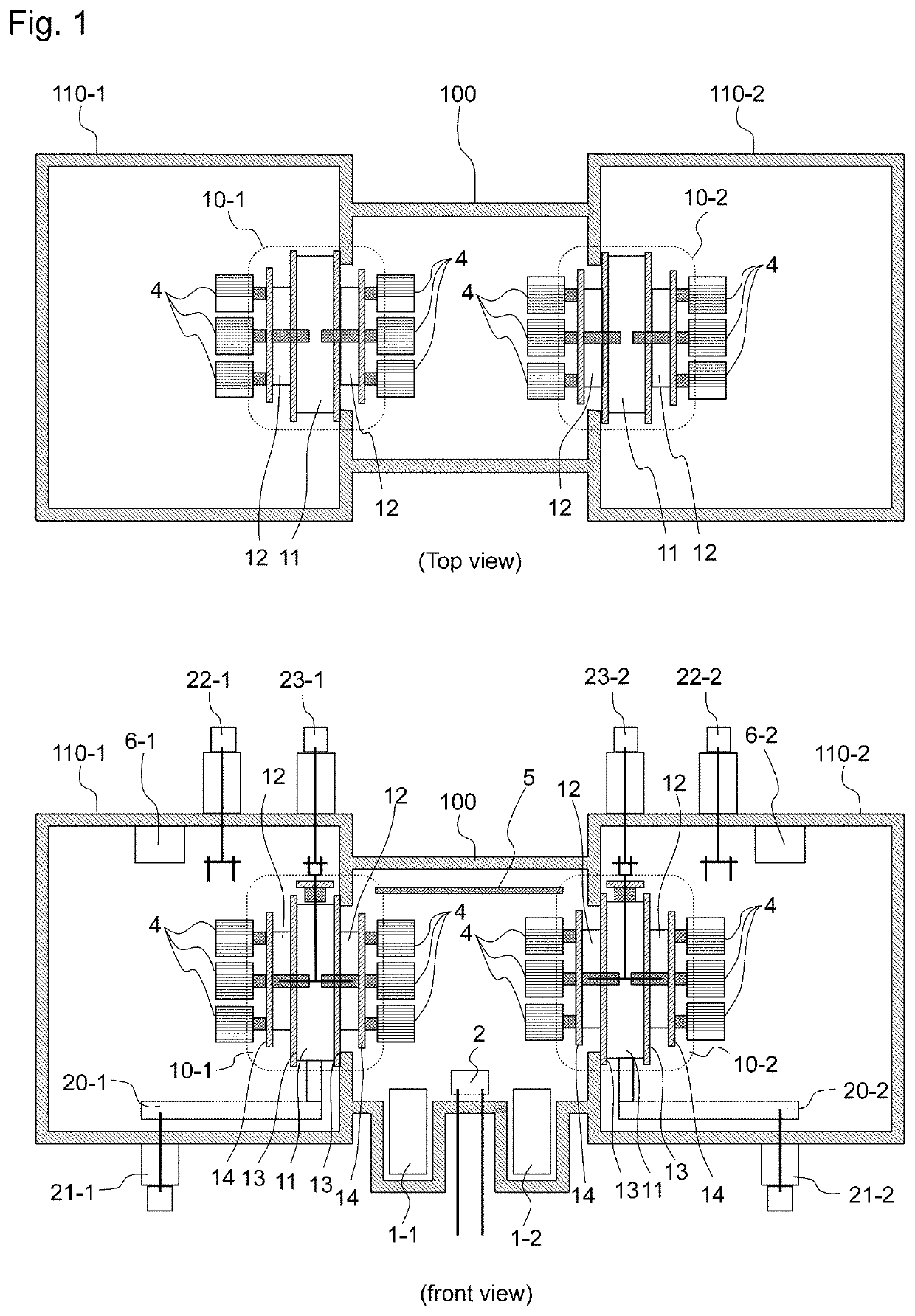
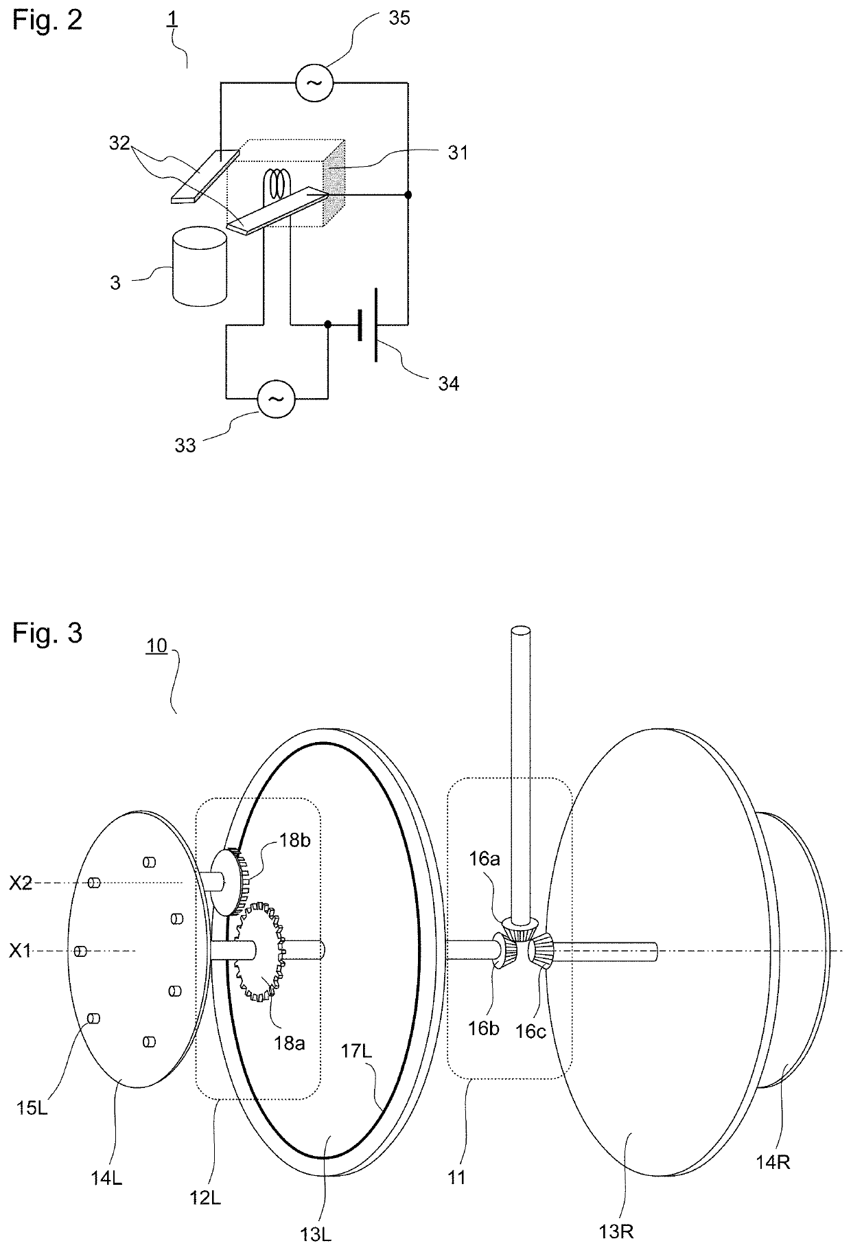
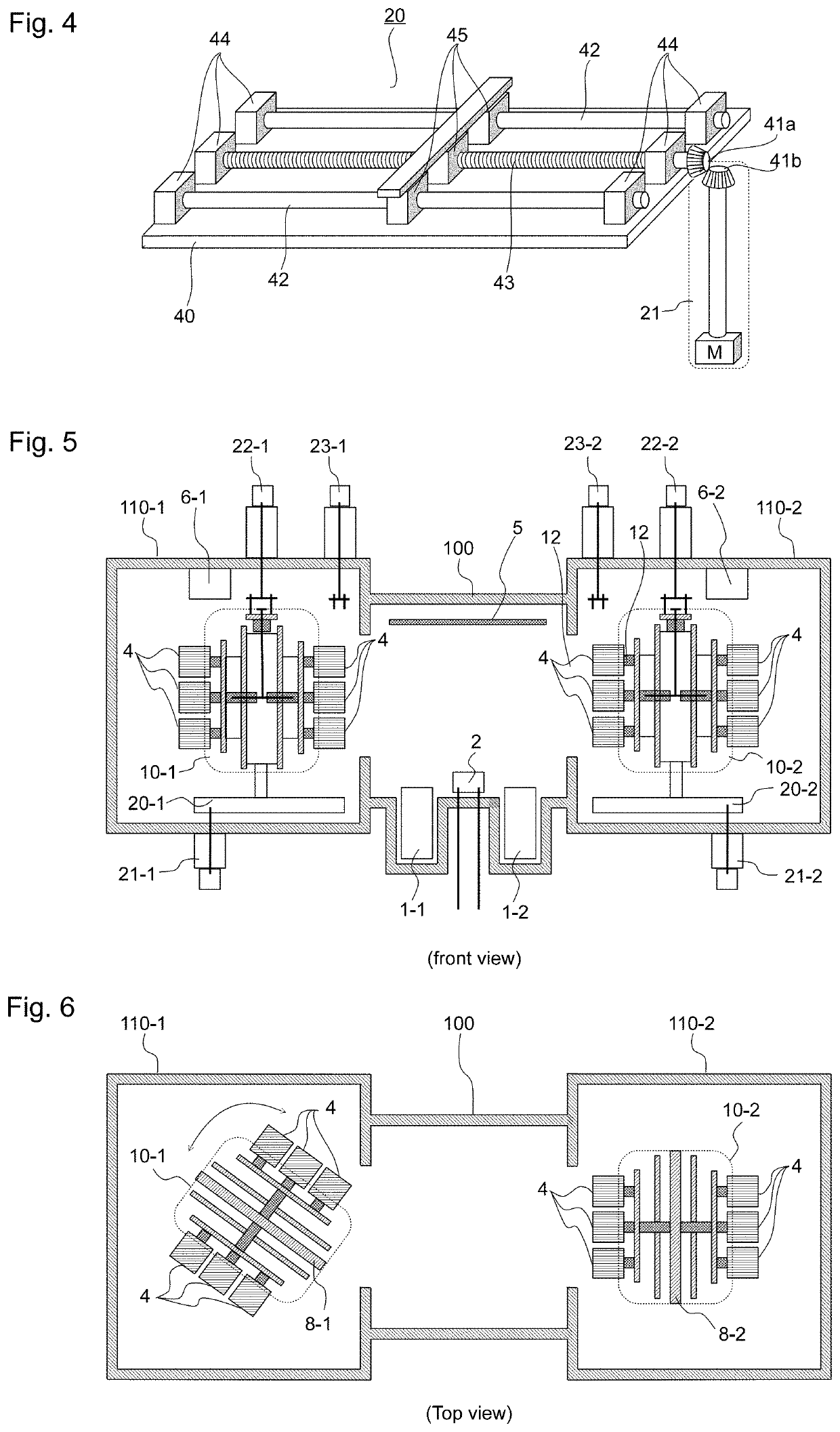
[0040]A typical embodiment of the invention is vapor deposition device for forming ceramic coating on a substrate (4) and includes a coating chamber (100), a loading chamber (110-1, 110-2), a substrate support mechanism (10), a horizontal moving mechanism (20), and a reversing mechanism (22). The vapor deposition device is configured as follows (FIG. 1).

[0041]The coating chamber and the loading chamber are connected individual...

first embodiment

[0059]FIG. 1 is a plan view illustrating a configuration example of vapor deposition device according to an embodiment of the present invention. The upper half of the drawing is a top view and the lower half is a front view, both of which are cross-sectional views of a central part of the device illustrating an internal structure of the device. To facilitate understanding of the invention, illustration of some of the structures is omitted, simplified, or moved from their original positions.

[0060]Although not particularly limited, examples are given regarding a substrate, a ceramic raw material, and a bond layer. The substrate is, for example, a heat-resistant super-alloy such as an Ni-based alloy, a Co-based alloy, or an Fe-based alloy. The ceramic raw material, i.e., the material of the ceramic coating, may be, for example, mainly zirconium oxide (zirconia; ZrO2) and hafnium oxide (hafnia; HfO2) to which Y2O3, MgO, CaO, TiO2, lanthanoid oxide, etc., may be added as a stabilizer. Th...

second embodiment

[0097]In the first embodiment, the vapor deposition device having two loading chambers 110-1 and 110-2 symmetrically located on both sides of the coating chamber 100 is described. However, the number of the loading chambers to be provided may be arbitrarily decided.

[0098]FIG. 20 is a configuration example of vapor deposition device provided with one loading chamber. A top view and a front view are given as in FIG. 1. Configuration and operation of the components are the same as those described in the first embodiment, so detailed description thereof will be omitted.

[0099]FIG. 21 is a configuration example of vapor deposition device provided with four loading chambers. Only the top view is given. Four loading chambers 110-1 to 110-4 are provided in four directions of one coating chambers 100. Each loading chamber includes a substrate support mechanism 10-1 to 10-4. Configuration and operation of each component are the same as those described in the first embodiment, so detailed descr...


PUM

PropertyMeasurementUnit
rotation speedsaaaaaaaaaa
elevated temperaturesaaaaaaaaaa
thermal expansion coefficientaaaaaaaaaa

Abstract

A vapor deposition device for forming a ceramic coating on a substrate, the device including a coating chamber, loading chambers, substrate support mechanisms, horizontal moving mechanisms, and reversing mechanisms, and configured as follows. The coating chamber and each loading chambers are connected individually to a vacuumizer and are connected to each other at their openings. In the coating chamber, an electron gun is provided that emits an electron beam with which the held ceramic raw material is irradiated. Each of the substrate support mechanisms includes left and right partition walls, a left substrate support plate on the left side of the left partition wall, and a right substrate support plate on the right side of the right partition wall. Each of the substrate support plates has multiple substrate mounting portions for mounting substrates thereon. The left and right substrate support plates are capable of revolving in a plane parallel to the left and right partition walls, and each of the multiple substrate mounting portions is capable of rotating. Each of the horizontal moving mechanisms is configured to cause the substrate support mechanism to move horizontally in the left-right direction between a vapor deposition position where one of the partition walls is in close contact with the opening and a reverse position where the left and right sides of the substrate support mechanism are reversed.

Description

TECHNICAL FIELD[0001]The present invention relates to vapor deposition device especially suitable for vapor-depositing ceramic on a metal substrate surface.BACKGROUND ART[0002]Metal substrates operating at elevated temperatures, such as rotor blades and stationary blades of a gas turbine, and blades of a combustor or a jet engine, are required to be coated with thermal barrier ceramic coatings. However, due to a difference in thermal expansion coefficient between the metal of the substrates and the coated ceramic caused by heat cycle applied to the substrates, the coating may crack or spall resulting in impairing durability. To address the issue of durability impairment, various techniques have been proposed.[0003]PTL 1 discloses a technique of layering a bond layer and thermal barrier ceramic coating on a metal substrate. The bond layer is regarded as providing corrosion resistance and oxidation resistance to the metal substrate, improving adhesiveness between the metal substrate a...

Claims


Application Information

Patent Timeline
Patent Type & Authority Applications(United States)
IPC IPC(8): C23C14/50C23C14/56C23C14/35
CPCC23C14/505C23C14/35C23C14/564C23C14/30C23C14/246C23C14/543C23C14/243C23C14/022C23C14/024C23C14/566C23C14/568
Inventor MATSUMOTO, KAZUHIDEWANG, HSIN-TSAI
Owner THERMALYTICA INC
Why Eureka
Try Eureka