

Integrated circuit package comprising a crossed dipole antenna
a technology of integrated circuit and dipole antenna, which is applied in the direction of polarised antenna unit combinations, individually energised antenna arrays, resonant antennas, etc., can solve the problem of inability to provide match polarization for circular polarized antennas
- Summary
- Abstract
- Description
- Claims
- Application Information
AI Technical Summary
Benefits of technology
Problems solved by technology
Method used
Image

Examples
Embodiment Construction
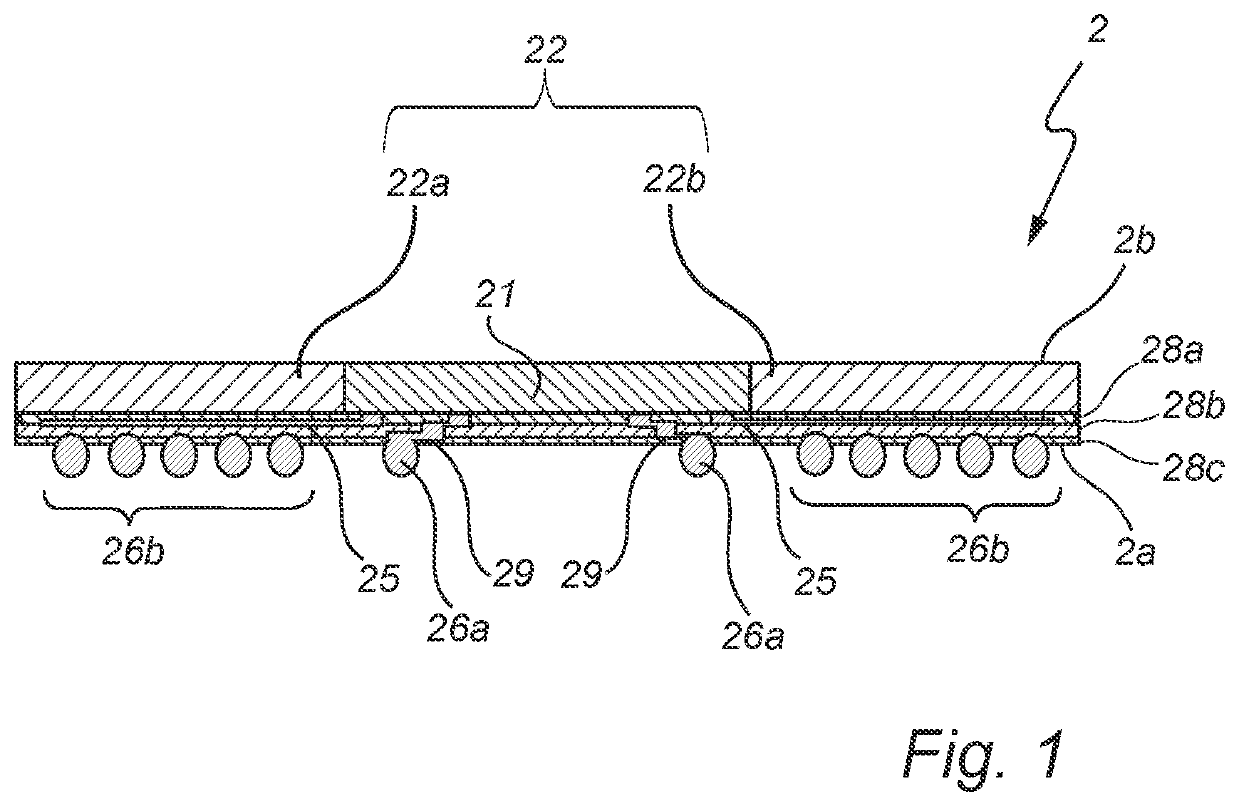
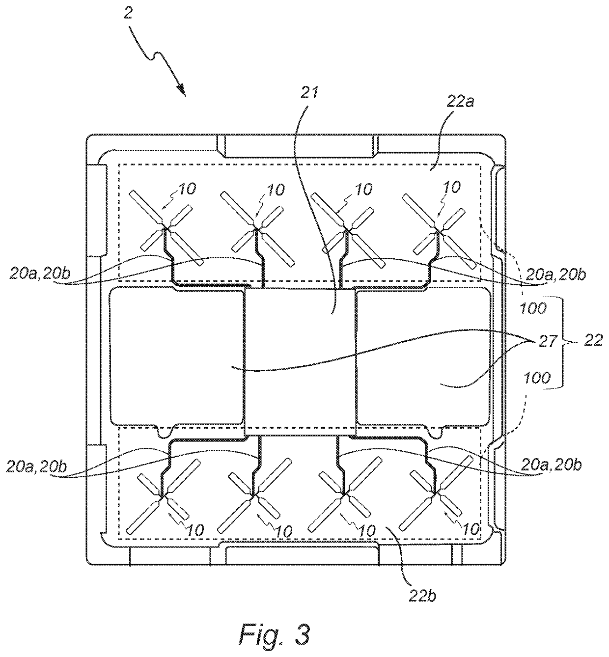
[0029]FIG. 1 schematically shows a cross-sectional view of an integrated circuit package 2 according to an exemplifying embodiment of the present invention. The integrated circuit package 2 comprises a first side 2a and second side 2b. The first side 2a and the second side 2b are opposite to each other. The first side 2a comprises bumps 26a, 26b. The bumps 26a, 26b comprise interconnect elements 26a. Further, the bumps 26a, 26b comprise dummy bumps 26b. The integrated circuit package 2 comprises three passivation layers. One of the passivation layers comprises the first side 2a. The passivation layers extend along the length and width of the integrated circuit package 2. The integrated circuit package 2 comprises a first redistribution metal layer, RDL, 25. The first RDL 25 is arranged between two of the passivation layers. The integrated circuit package 2 comprises two antenna arrays 100, see
[0030]FIG. 3. It is to be understood that each antenna array 100 may comprise a plurality o...
PUM
 Abstract
Description
Claims
Application Information