Eureka AIR delivers breakthrough ideas for toughest innovation challenges, trusted by R&D personnel around the world.

Semiconductor laser device structures and methods of fabrication thereof

a laser device and semiconductor technology, applied in semiconductor lasers, laser optical resonator construction, laser details, etc., can solve the problems of inconvenient use of metal reflectors on the back facet that block light completely, high reflectivity metal reflectors that cannot be used in multi-transverse mode operation, and high cost of facet coatings

Pending Publication Date: 2022-09-29
ELECTROPHOTONIC IC INC
View PDF0 Cites 0 Cited by
  • Summary
  • Abstract
  • Description
  • Claims
  • Application Information

AI Technical Summary

Benefits of technology

The present invention aims to solve issues with existing device structures and fabrication methods. It provides a way for high-performance operation and high yield of both single lateral mode and single longitudinal mode operation. The invention also allows for improved phase-alignment, higher-order mode suppression, lower cost, and improved reliability. It includes a method where a metal layer on the top surface of the mesa is patterned to form an etch mask for the SEG, resulting in improved ohmic placement for current flow through the active region.

Problems solved by technology

However, under some operating conditions, these lasers demonstrate unacceptable multi-transverse mode operation, particularly when operated without transition waveguides and spot size converters.
However, facet coating is expensive.
A high reflectivity metal reflector on the back facet that blocks light entirely is not suitable if back-facet power monitoring (BPM) is required.
Another issue is that any misalignment and phase variations between the teeth of the SEG and the reflective facets can lead to a reduced yield of lasers that meet acceptable performance requirements, with a corresponding increase in cost per acceptable die.
For example, electron-beam (e-beam) writing of grating structures tends to be expensive, and not as readily accessible as photolithography with stepper mask defined gratings.

Method used


Image

  • Semiconductor laser device structures and methods of fabrication thereof
  • Semiconductor laser device structures and methods of fabrication thereof
  • Semiconductor laser device structures and methods of fabrication thereof

Examples


first embodiment

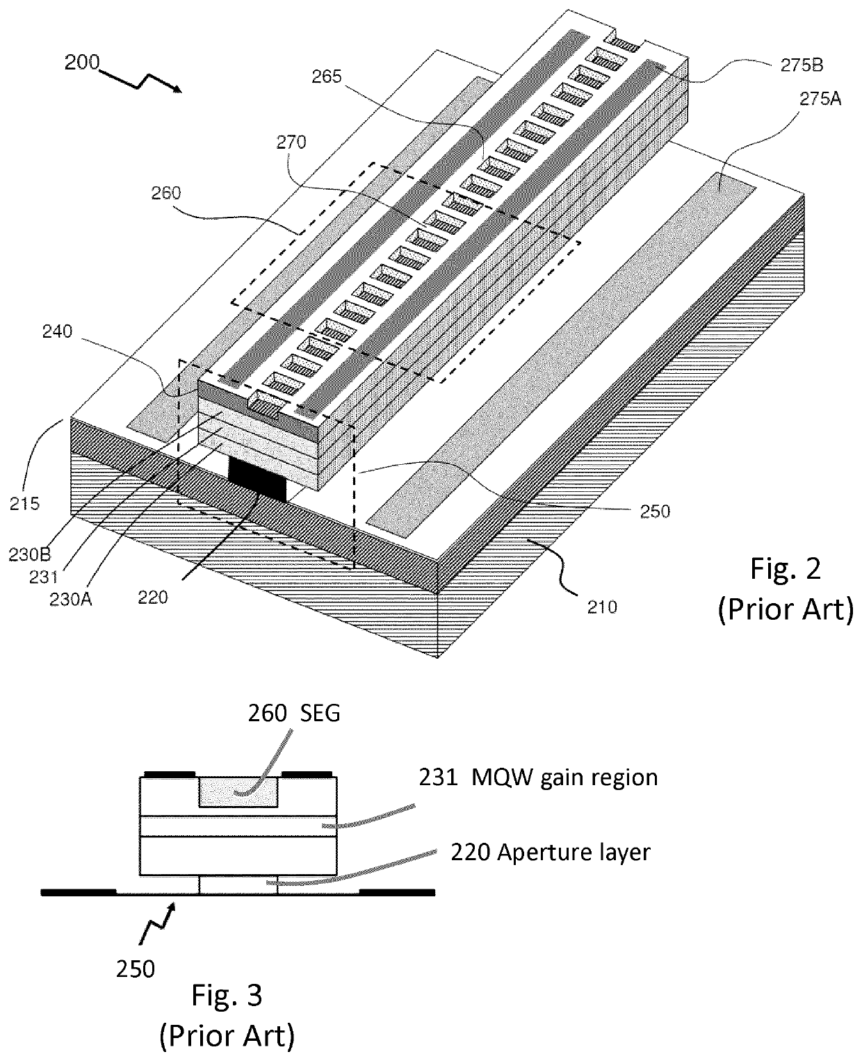
[0064]FIG. 6A is a schematic diagram of a device structure comprising a VC SEG DFB laser with a phase-aligned mode-selective reflector of a first embodiment, comprising a structured reflector in the form of a single interface mirror structure. As illustrated schematically, the laser mesa comprises a DFB SEG etched along the length of the mesa, e.g. similar to that shown in FIG. 2. The back-facet of the laser structure is formed by etching a trench, which in this embodiment it is a simple rectangular trench. One wall of the trench that forms the back-facet of the laser waveguide is spaced a predetermined distance from the grating, e.g. a multiple of λ / 4, to provide a phase-adjust region, and a spatially patterned reflector is provided on the back-facet. The spatially patterned back reflector is configured to selectively reflect the TE0 mode, e.g. formed as a thin stripe reflector having dimensions which optimize reflection of the TE0 mode relative to the higher modes. Other areas of ...

third embodiment

[0068]FIG. 7A is a schematic diagram of a device structure comprising a VC SEG DFB laser with a phase-aligned mode-selective reflector of a third embodiment comprising a multi-interface (DBR) type structure. In this structure, a spatially patterned back-facet reflector coating is replaced with a distributed Bragg reflector structure (DBR structure), which comprises a series of etched trenches defining a multi-interface reflector. In this embodiment, the etched trenches are rectangular trenches. This structure also includes a phase-adjust region between the DFB grating teeth of the laser and the DBR structure.

fourth embodiment

[0069]FIG. 7B is a schematic diagram of a device structure comprising a VC SEG DFB laser with a phase-aligned mode-selective reflector of a fourth embodiment comprising a multi-interface (DBR) type structure, wherein the etched trenches defining the multi-interface reflector are a series of trapezoidal trenches, separated from the DFB grating teeth of the laser by a phase-adjust region. In variants of this embodiment, the trapezoidal trenches may have curved sidewalls, and other geometric forms of trenches with flat or curved sidewalls may be used, as appropriate. As noted in FIG. 7B, in practice the trenches may be shaped to to avoid acute angles at the corners.

[0070]For each of the structures shown in FIGS. 7A and 7B, the dimensions and coating materials of the multi-interface DBR structure are configured to provide higher feedback of the fundamental TE0 mode relative to higher order transverse modes, e.g. TE1, TE2, etc.

[0071]The mode selective filter may comprise laterally define...


PUM


Abstract

Semiconductor device structures comprising laser diode cavities with at least one of a mode-selective filter and a phase-alignment element, and methods for their fabrication, are disclosed. An example device structure comprises a surface-etched grating distributed-feedback (SEG DFB) laser with a mode-selective reflector structure. The reflector structure is designed to provide higher pot feedback of the fundamental TE0 mode and suppression of higher order mode effects. The reflector structure may be a single interface (single facet) mirror type reflector comprising a spatially patterned reflector, or a multi-interface distributed Bragg reflector (DBR). A phase alignment element may be included to provide precise optical phase control. A photodetector for back-facet power monitoring may be included. A method of fabrication is disclosed, based on a self-aligned process in which DBR features are included on the same mask that is used for the DFB laser grating.

Description

CROSS-REFERENCE TO RELATED APPLICATION(S)[0001]This application claims priority from U.S. provisional patent application No. 62 / 912,148, filed Oct. 8, 2019, entitled “Semiconductor Laser Device Structures and Methods of Fabrication thereof”, which is incorporated herein by reference in its entirety.TECHNICAL FIELD[0002]The present invention relates to semiconductor device structures comprising laser diodes and methods for their fabrication, and more particularly to surface-etched grating (SEG) distributed feedback (DFB) lasers and methods for their fabrication.BACKGROUND[0003]US2012 / 0106583 published May 3, 2012 (Watson et al.), entitled “Vertically-Coupled Surface-Etched-Grating DFB laser”, discloses a laser diode structure having a vertically coupled (VC) surface-etched-grating (SEG). This device structure is compatible with single-growth monolithic integration for photonic integrated circuits (PIC) implemented with InP and related III-V semiconductor materials.[0004]It has been d...

Claims


Application Information

Patent Timeline
IPC IPC(8): H01S5/028H01S5/10H01S5/125H01S5/026
CPCH01S5/0287H01S5/1082H01S5/125H01S5/0264H01S2301/166H01S5/1237H01S5/1231H01S5/34306H01S5/2045H01S5/12
Inventor CLAYTON, RICHARD D.HAGLEY, WILLIAM A.TAROF, LAWRENCE E.
Owner ELECTROPHOTONIC IC INC
Why Eureka
Eureka Blog
Learn More