Hemming method and apparatus

a technology of hem flange and hammer, which is applied in the direction of forging/pressing/hammering apparatus, manufacturing tools, metal-working machine components, etc., can solve the problems of additional equipment, damage or distort the assembled panels, and the hem flange may not be sufficient to prevent the inner panel, etc., to improve the quality of appearance tolerances, accurate, precise, automatic control and high efficiency

Inactive Publication Date: 2000-02-29
UNOVA IP
View PDF12 Cites 93 Cited by
  • Summary
  • Abstract
  • Description
  • Claims
  • Application Information

AI Technical Summary

Benefits of technology

Accordingly, among the objects, features and advantages of the present invention are to provide an improved method, and improved apparatus for performing such method, and an improved interlock joint made by such method and apparatus, which overcome the aforementioned problems of interlock holes or beads de-registering with PLP points, eliminates the read through problem while obtaining a precise and strong mechan

Problems solved by technology

It has been recognized in the prior art that this hem flanging together of the panels may not be sufficient to prevent the inner panel from sliding relative to the outer panel.
In each of these cases, the operation require additional equipment and inevitably damages or distorts the assembled panels, which in turn requires refinishing of the metal to correct the imperfections which will become visible i.e., "read through", when the outer panel is painted.
Although this mechanical coined interlock technique eliminates the additional investment and labor of a welding operation, it nonetheless has been found to distort the outer panel because the punching burrs or upset edge on the inner panel outboard side around each punched hole in the inner panel causes read through on the exterior or outboard surface of the outer panel.
However, the '734 bead-on-bead method does not provide the same mechanical interlock strength as the aforementioned punched hole method in which the outer panel flange is pressed coined into the hole of the inner panel as shown in FIG. 4 of the '734 patent.
Additionally, the '734 method necessarily results in an undesirable overall increase in the thickness dimension of the hemmed flange as compared to the prior punched hole method.
Another problem common to both such prior art methods has been found to arise as a result of the interlock holes or the raised interlock beads being initially formed in the edge of the inner panel concurrently with punching principal locating point (PLP) holes.
Moreover, shifts in location are not necessarily uniformly predictable from part to part.
De-registry of the outer panel metal, as worked by the forming tool, with its intended location relative to the interlock hole

Method used


Image

  • Hemming method and apparatus
  • Hemming method and apparatus
  • Hemming method and apparatus

Examples


Embodiment Construction

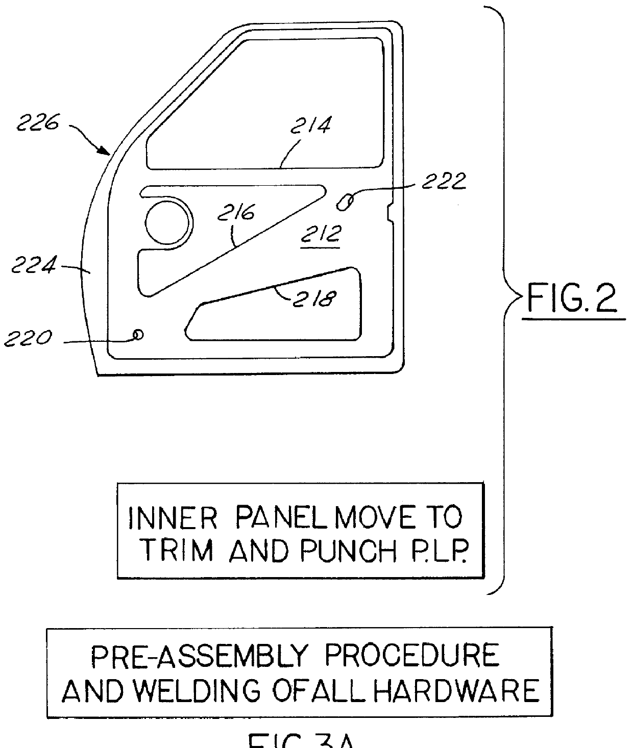
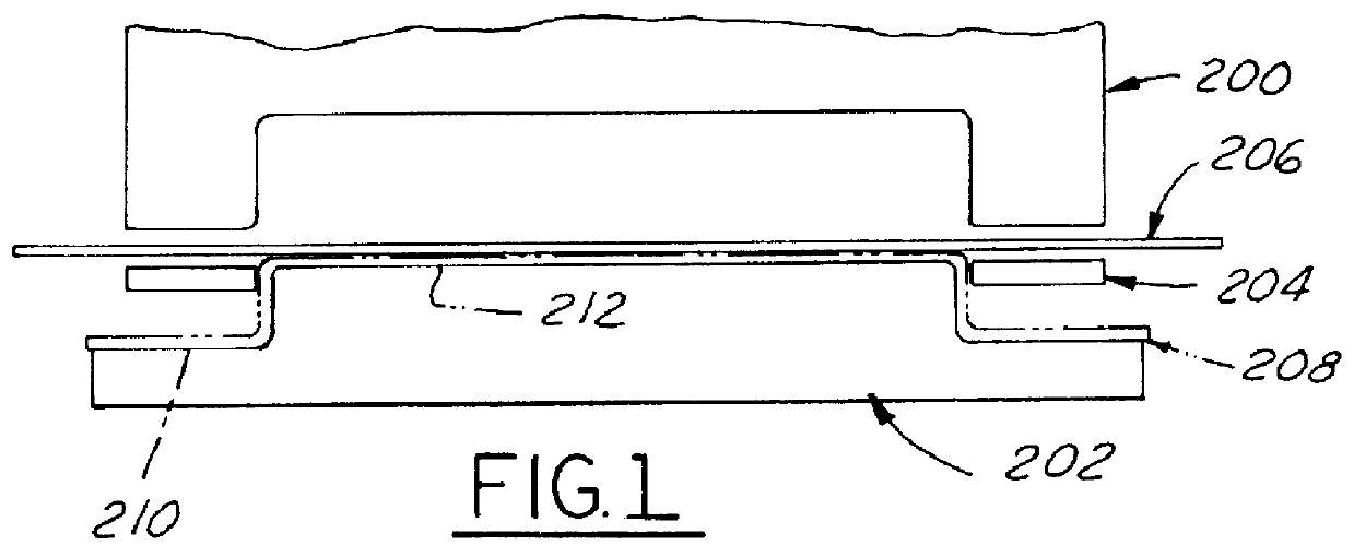
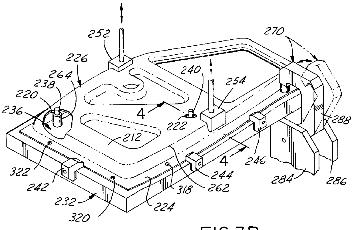
Referring in more detail to the accompanying drawings, FIGS. 1-27 generally illustrate in sequence the improved method, the conventional as well as improved apparatus employed in accordance with the invention for performing the method, as well as the improved hemmed flanged interlock joint produced by such method and apparatus in accordance with the invention. The method can be generally subdivided into three phases as applied to a working example of a front (starboard or right-hand) side door assembly for an automotive vehicle: (1) the construction of a door inner panel subassembly as partially illustrated in FIGS. 1-10; (2) then marrying of the door inner panel subassembly to a preformed door outer panel so as to be held temporarily assembled together by crimps in the flange lip of the outer door panel, as illustrated in FIGS. 11 and 12; and (3) then the operations of pre-hemming, final hemming and flange interlocking of the married panels in a hemming station as illustrated in FI...


PUM

PropertyMeasurementUnit
Sizeaaaaaaaaaa
Shapeaaaaaaaaaa
Dimensionaaaaaaaaaa

Abstract

Improved method and apparatus for interlocking hemmed together edges of inner and outer vehicle body panels with an improved interlock joint. The inner panel blank is draw stamped and provided with PLP holes in a stamping press. A plurality of conventional hardware components are then welded to the inner panel. Then interlock holes are formed by a piercing tool moving through the inner panel border from its outboard to its inboard side while the inner panel is held by clamps and PLP pins. The hole piercing punch thus leaves cold worked upset material slightly raised inboard, rather than outboard, around the pierced interlock hole margin. Then the inner panel subassembly is married to the outer panel and transferred to a hemming station and again precisely clamped and positioned by PLP pins, whereupon hemming press gates are operable for hemming the flange lip of the outer panel over the inner panel border. The final hemming steel of each gate carries staking punches that individually strike a precision registered portion of such hemmed lip to deform it into locking engagement with the associated interlock hole. The upset material is thus flattened and accurately worked into embedment into the interior surface of the hemmed flange lip, rather than into the interior surface of the outer panel, thereby avoiding creating read through problems on the outer panel.

Description

This invention relates to hemming of sheet metal, and more particularly to a method and apparatus for forming a hem on an edge flange of a sheet of a multi-ply structural sheet member, such as a vehicle body panel.It is well known to construct motor vehicle body doors, hoods, fenders, tailgates, trunk and deck lids by stamping an outer sheet metal panel and separately stamping an inner sheet metal reinforcing panel with an outer periphery generally matching that of the outer panel, and then joining the two panels together by hemming a flange-over, the periphery of the outer panel over an adjacent edge of the inner panel to thereby secure the panels together. The inner and outer panels are individually stamped to their desired size and shape, with the outer panel being slightly larger than the inner panel to provide a border flange portion along the edge of the outer panel having an upstanding lip which can be folded over the peripheral edge of the inner panel to define the hem flang...

Claims


Application Information

Patent Timeline
IPC IPC(8): B21D39/02
CPCB21D39/021B21D39/026Y10T29/49915Y10T29/49904Y10T29/49936Y10T29/49895
Inventor HARTLEY, WILLIAM R.
Owner UNOVA IP
Why Eureka
Try Eureka