Time-temperature indicator device and method of manufacture

a time-temperature indicator and indicator device technology, applied in the direction of thermometer details, instruments, heat measurement, etc., can solve the problems of device not indicating an expired condition, device not readily accepted for use in enforcing regulations, and severe limitations in practical valu

Inactive Publication Date: 2000-03-28
TEMPTIME CORP
View PDF13 Cites 278 Cited by
  • Summary
  • Abstract
  • Description
  • Claims
  • Application Information

AI Technical Summary

Benefits of technology

to provide a time-temperature indicator label for signalling the exposure of a product when such exposure has exceeded the permissible exposure for a period of time above a pre-determined temperature. The label is devised so that time exposure is integr...

Problems solved by technology

Indicators known in the art have not been readily accepted for use in enforcing regulations because of the cost of the indicating devices and because the devices did not directly give an indication of temperature exposure as described in the regulation.
Further, such devices might not signal an expired condition if the pre-determined limit had been exceeded because the devices develop a signal from an integrated exposure that generally will not react very quickly above said pre-determined temperature.
Because these indicator labels change irreversibly and instantly upon exposure to a pre-determined temperature, their practical value is severely limited.
It is readily conceivable that a devious individual could walk down the aisle and simply touch each food product at the indicating spot for a matter of seconds, causing the color indicator to ...

Method used


Image

  • Time-temperature indicator device and method of manufacture
  • Time-temperature indicator device and method of manufacture
  • Time-temperature indicator device and method of manufacture

Examples


example 1

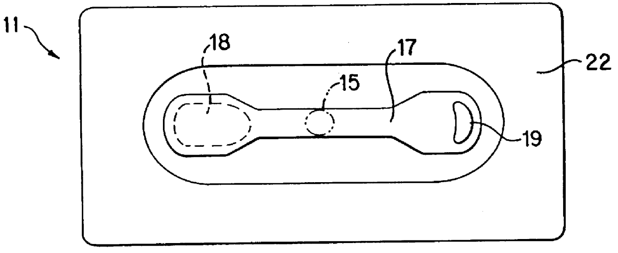
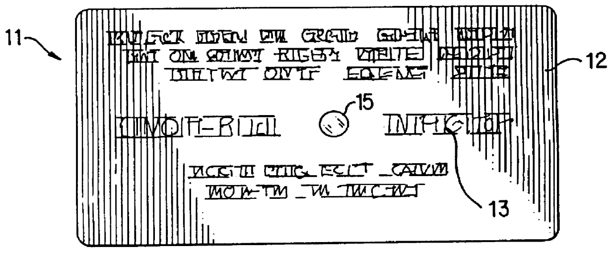
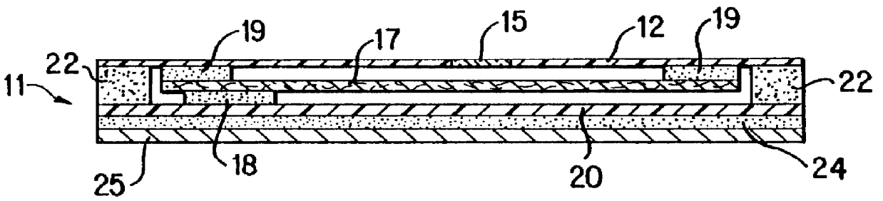
A Gallus R250 (Gallus Inc. Newtown, Pa.) printing machine was used to prepare a time-temperature device in accordance with the invention. Ahlstrom filter paper grade #950 as the wicking element was screen printed to contact areas 19 (see FIG. 3 of the drawing) with RC 2008 UV-cured laminating adhesive from Electromek Co. Carlstadt, N.J. The printed paper was laminated with 0.002" clear polyester film 12. This film was screen printed on the top surface with an green ink with a 1 / 8" diameter hole in the print to form the viewing window 15. A legend comprising instructions for the use of the device was then printed. The filter paper being affixed to the top film layer was die cut around the two attachment points 19 to the top layer film without puncturing the top layer forming the wicking member 17. The wicking member 17 in this example was produced in a convenient barbell-type shape and the scrap matrix was removed. Various other shapes such as oval, circular, spiral may also be used ...

example 2

A device was prepared using the top layer 12 with the die cut wicking member 17 from Example 1. The perimeter seal 22 was screen printed manually on 12 with a UV cured self-adhesive IRR88 supplied by UCB Chemicals, Smyma, Ga. The heat-fusible, organic substance was a mixture of n-tetradecane (melting point 5.8.degree. C., 42.4.degree. F.) with 2% Solvent Red "O" dye. 3 .mu.L of this mixture was volummetrically deposited on one end of wicking member 17 and immediately sealed with a white polyester backing layer with self-adhesive layer and release liner. The assembled device was immediately placed in a freezer (-18.degree. C., 0.degree. F.) for several hours. This device was placed on a commercially available foam refrigerant pack sold by FCC Packaging, Inc. Medfield, Mass., that had been stored at 2.9.degree. C. (37.2.degree. F.). This pack was used to simulate a chilled food product. The simulated food product with indicator device attached thereto was stored at 2.9.+-.0.2.degree. ...

example 3

A device was prepared using the top layer substrate 12 with the wicking member 17 from Example 1. The perimeter seal 22 was screen printed manually on 12 with a water-based self-adhesive WPS 4211 from Elektromek. Microcapsules containing a mixture of 6 parts n-tetradecane and 2 parts n-tridecane with 2.5% blue #36 dye were prepared by Lipo Technologies, Inc. Dayton, Ohio. The capsules were composed of 85% core material (alkanes and dye) and 15% wall material made from gelatin. The capsules were 75.mu. mean size and were slurried at a 30% concentration in a 15% solution of nitrocellulose in butyl cellosolve. This suspension of capsules was manually screen printed on the end of wicking member 17 and dried in an oven to form an activatable layer 18 heat-fusible substance. The perimeter seal 22 was formed as in example 2, utilizing the same adhesives and backing layer 20. The construction of this type was stored at room temperature for a week with no appearance of the color in the viewi...


PUM


Abstract

A time-temperature indicator label for measuring the length of time to which a product has been exposed to a temperature above a pre-determined temperature is provided. The period of time of exposure is integrated with the temperature to which the indicator is exposed. The label is a composite of a plurality of layers adapted to be adhered at its underside to a product container. The label includes a printable surface layer, a longitudinal wicking strip that is adhered underneath the surface layer substantially at the opposite extremities only of the wicking strip and a lower substrate layer forming an envelope with said surface layer. A heat-fusible substance, which melts and flows above a pre-determined temperature, is applied on the surface of the wicking strip contiguous to at least one of the ends of the wicking member. When the heat-fusible substance is exposed to a temperature above the pre-determined temperature, the heat-fusible substance flows along the length of the wicking member. The label has a printable surface layer and is sealed at its peripheral edge to the peripheral edge of the substrate layer. These layers encapsulate the wicking member and the heat-fusible substance. The surface layer is provided with a sight window at an intermediate location over the wicking member through which the progress of flow on the wicking member is observed.

Description

This invention relates to a novel, easily applied time-temperature indicator label that has a thickness and flexure essentially comparable to those features of conventional labels. The invention provides an economical and practical, self-adhesive means to measure elapsed time above a pre-determined temperature. The label of this invention possesses sufficient suppleness to allow attachment by means of a self-adhesive material to a variety of package shapes and contours, such as, for example, use as a band label on a bottle of wine, or as a label on a package of food. The label comprises a porous strip of wicking material that is incorporated within and attached at both ends to a supporting film, the strip of wicking material being completely sealed around its perimeter within the supporting film. The wicking material carries a heat-fusible substance capable of migrating along said wick at temperatures above the melting range of the heat-fusible substance. The visibility of migration...

Claims


Application Information

Patent Timeline
IPC IPC(8): G01K3/00G01K3/04
CPCG01K3/04
Inventor PRUSIK, THADDEUSARNOLD, RAYMOND M.FIELDS, STEPHEN C.
Owner TEMPTIME CORP
Why Eureka
Try Eureka