

Patch clamp apparatus and technique having high throughput and low fluid volume requirements
a technology of fluid volume requirements and clamping apparatus, which is applied in the direction of liquid/fluent solid measurement, instruments, electrochemical variables of materials, etc., can solve the problems of limited work, patch clamping technique, and pharmacological screening have been limited in the number of compounds that could be tested per day (typically no more than). , to reduce the time required for testing procedure, the effect of low sample volume and reduced total volum
- Summary
- Abstract
- Description
- Claims
- Application Information
AI Technical Summary
Benefits of technology
Problems solved by technology
Method used
Image

Examples
example 2
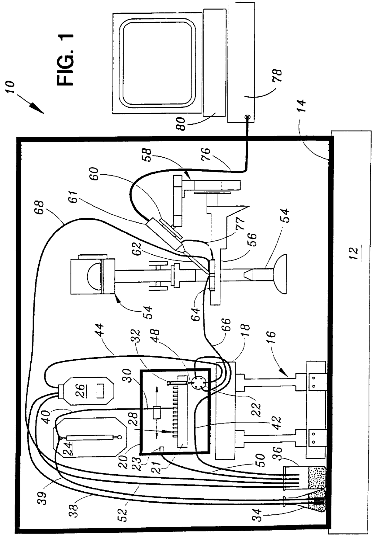
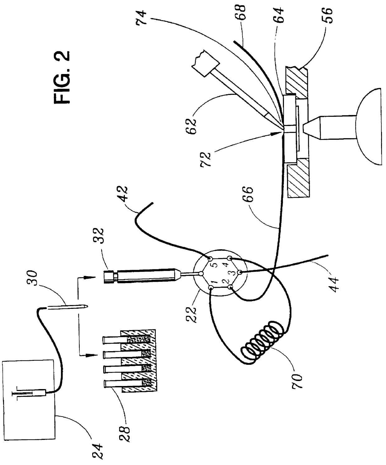
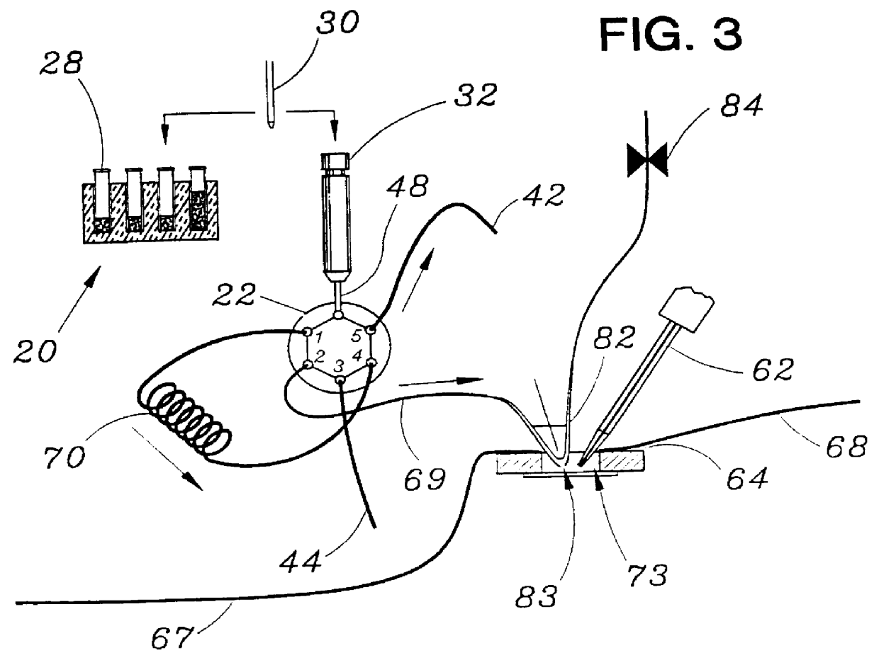
STOP-FLOW TECHNIQUE: The potassium current of a cultured human coronary smooth muscle cell was determined in an excised inside out patch by the stop-flow technique utilizing an apparatus as disclosed above and diagramed in FIGS. 7-10, comprising an autosampler, syringe pump, and microperfusion chamber having a volume of 12 .mu.l.
The composition of the pipette and bath solutions was:
Pipette: KCl (140 mM), CaCl.sub.2 (1 mM), MgCl.sub.2 (1 mM), EGTA (1.3 mM), HEPES (10 mM).
Bath: KCl (140 mM), CaCl.sub.2 (1 mM), MgCl.sub.2 (1 mM), EGTA from 1.07 mM to 2.0 mM. The free Ca.sup.2+ concentration is determined by the concentration of EGTA. All test compounds were dissolved in bath solution with 0.3 .mu.M free Ca.sup.2+.
The effects of 25 unknown compounds on calcium activated potassium channels were tested and reported in FIG. 12. In the experimental protocol, successive unknown compounds (open circles) were perfused (300 .mu.l) with intermittent washout with saline solution (filled circles)....
PUM
| Property | Measurement | Unit |
|---|---|---|
| volume | aaaaa | aaaaa |
| volume | aaaaa | aaaaa |
| volume | aaaaa | aaaaa |
Abstract
Description
Claims
Application Information