

Fuel supply system with fuel evaporation prevention
- Summary
- Abstract
- Description
- Claims
- Application Information
AI Technical Summary
Benefits of technology
Problems solved by technology
Method used
Image

Examples
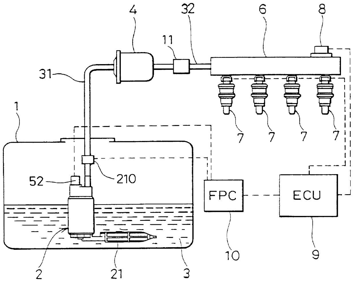
first embodiment
(Modification of First Embodiment)
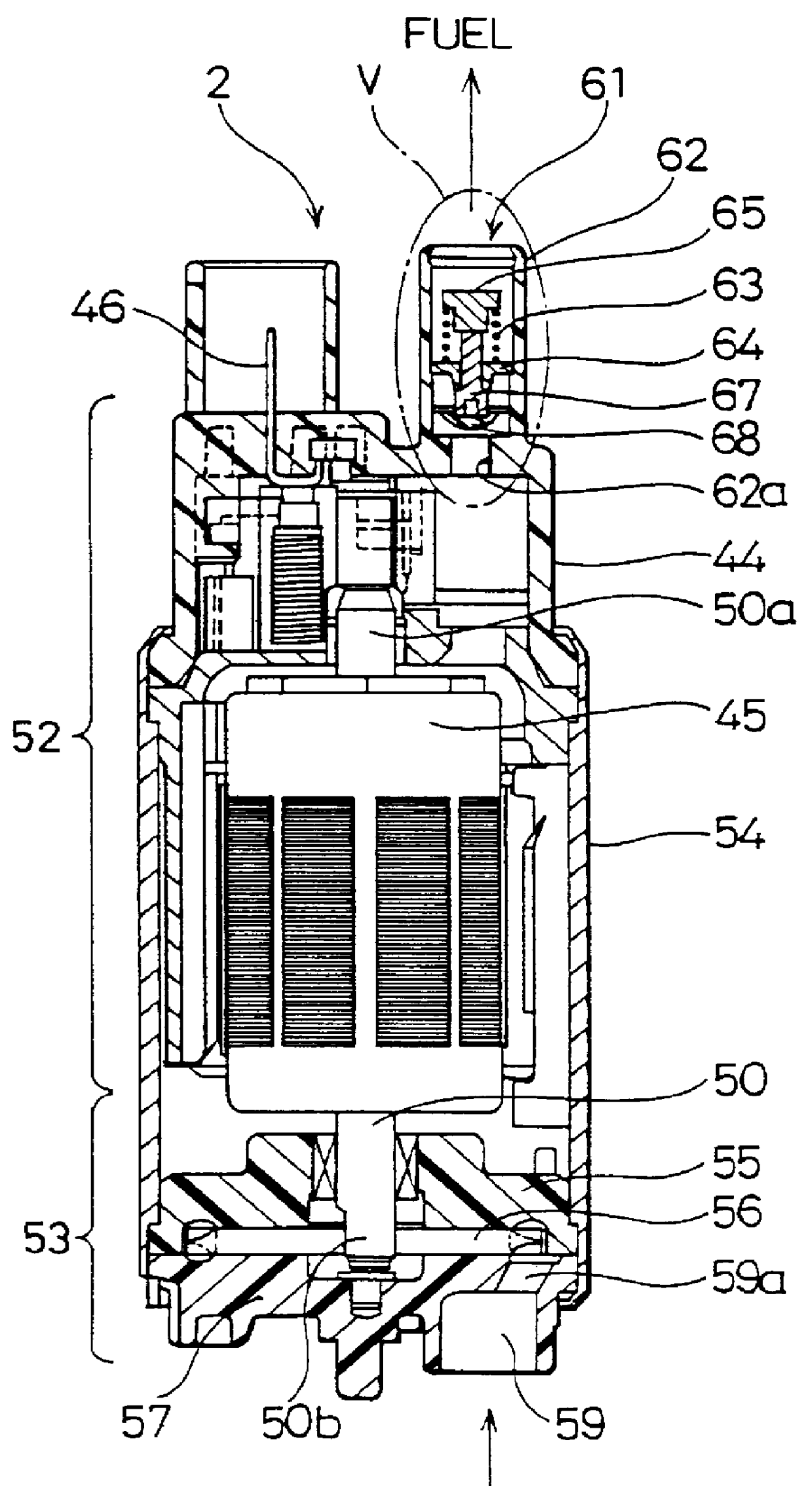
A modification of the first embodiment where a fuel control valve is integrally formed with the fuel pump is hereinafter described with reference to FIGS. 4 and 5.
The fuel pump 2 is composed of a direct current motor 52 and a pump 53 as shown in FIG. 4. An armature 45 rotated responsive to electric power supplied to terminal 46 is contained in housing 54. One end 50a of shaft 50 fixed to armature 45 is rotatably supported.
As for pump 53, casing 55 and pump cover 57 are fixed inside housing 54 by press-fitting or the like. An impeller 56 located between casing 55 and pump cover 57 and fixed to the other end 50b of shaft 50 is rotatably contained between casing 55 and pump cover 57. A predetermined minute space is provided between impeller 56 and casing 55 and pump cover 57 surrounding its periphery, thereby, impeller 56 can rotate while sliding in casing 55 and pump cover 57.
The pump cover 57 has a communicating hole 59a passing through the fuel flow...
second embodiment
(SECOND EMBODIMENT)
A fuel control valve according to a second embodiment of the present invention is hereinafter described with reference to FIGS. 9 and 10A-10C.
A fuel control valve 70 of the second embodiment has a discharging port of a fuel pump in the same manner as in the modified embodiment (FIGS. 4 and 5) of the first embodiment.
A housing 71 of fuel control valve 70 is integrally molded with the housing of a fuel pump with resin and a fuel passage is formed passing through the axial direction of housing 71. The housing 71 is composed of a smaller diameter portion 71a and a larger diameter portion 71b whose inner diameter is larger than that of the smaller diameter portion 71a in the range from the fuel upstream side to the fuel downstream side. The diameter of the opening of the larger diameter portion 71b becomes smaller toward the fuel downstream side.
An annular member 72 as a supporting member is cylindrically formed and contained in the inner periphery of the larger diamet...
third embodiment
(THIRD EMBODIMENT)
A fuel control valve according to a third embodiment of the present invention is hereinafter described with reference to FIGS. 12 and 13A-13C.
A housing 91 of fuel control valve 90 is integrally molded with the housing of the fuel pump with resin and a fuel passage is formed passing in the axial direction of housing 91. The housing 91 is composed of smaller diameter portion 91a and larger diameter portion 91b whose inner diameter is larger than smaller diameter portion 91a from the fuel upstream side to the fuel downstream side. The diameter of the opening of the larger diameter portion 91b becomes smaller toward the fuel downstream side.
The outer periphery of a flat spring 92 is fixed to the inner peripheral wall of larger diameter portion 91b whereas the inner periphery of flat spring 92 is fixed to an engaging member 93. The engaging member 93 is supported by flat spring 92 reciprocably. A sliding hole 93a passes in the axial direction of the engaging member 93 a...
PUM
 Abstract
Description
Claims
Application Information