Artificial neural canal

a neural canal and artificial tube technology, applied in the field of artificial neural canals, can solve the problems of inconvenient shape of the tube, excessive degradation and absorption of the tube, etc., and achieve the effect of easy control of the degree of crosslinking

Inactive Publication Date: 2000-07-18
TAPIC INT
View PDF2 Cites 121 Cited by
  • Summary
  • Abstract
  • Description
  • Claims
  • Application Information

AI Technical Summary

Benefits of technology

Next, crosslinking treatment is preferably performed on tubes 10, 20 composed of a material being biodegradable and absorbable in vivo prepared in the manner described above. Crosslinking treatment is advantageous for the artificial tube for nerve of the present invention because it maintains the shape of the tube and prevents invasion of cells from outside the artificial tube for nerve during the time until the peripheral nerve is finished regenerating.
Although varying according to the length of the severed nerve portion that requires regeneration, crosslinking treatment is performed for 1-3 months after application in the body to an extent that the shape of the tube is retained. Although examples of crosslinking methods include gamma ray crosslinking, ultraviolet ray crosslinking, electron beam crosslinking, thermal dehydration crosslinking, glutaraldehyde crosslinking, epoxy crosslinking and water-soluble carbodiimide crosslinking, thermal dehydration crosslinking is preferable because it is easy to control the degree of crosslinking and does not have an effect on the body even when used for crosslinking treatment. Crosslinking treatment is performed in a vacuum at a temperature of, for example, about 105-150.degree. C., preferably about 120-150.degree. C., and particularly preferably about 140.degree. C. for, for example, about 6-24 hours, preferably about 6-12 hours and particularly preferably about 12 hours.

Problems solved by technology

If the membrane thickness exceeds 3 mm, the tube obstructs regeneration of body tissue, and if the membrane thickness is less than 0.1 mm, degradation and absorption of the tube proceeds too rapidly, and the shape of the tube is not maintained until the nerve finishes regenerating.

Method used


Image

  • Artificial neural canal
  • Artificial neural canal

Examples


example 2

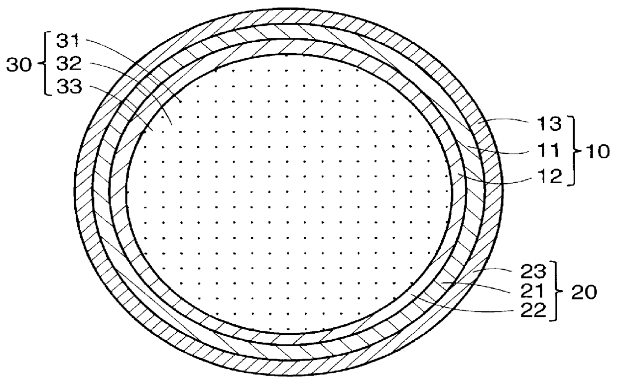
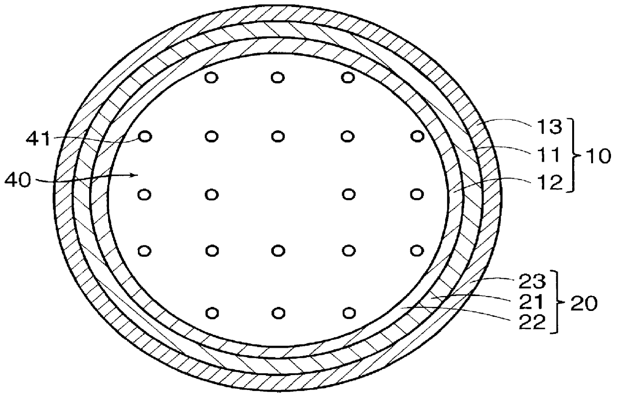
As a result of immersing Teflon rod having a length of about 10 cm and diameter of about 4-5 mm in a 1 N hydrochloric acid solution containing about 1 wt % of enzyme-solubilized collagen originating in pig skin and then taking them out of the above-mentioned solution, a collagen hydrochloric acid solution layer having a thickness of about 10 mm was formed on the surface of the Teflon rod, after which it was frozen at about 0.degree. C. for about 12 hours. The rod was then freeze-dried at about 0.degree. C. for about 24 hours in a vacuum to transform the collagen hydrochloric acid solution layer into a fine fibrous collagen layer. The Teflon rod having a fine fibrous collagen layer formed on the surface was then compressed with a press to compress the fine fibrous collagen layer to a thickness of about 1 mm. Next, the compressed fine fibrous collagen layer was removed from the Teflon rod, and the tube composed of this fine fibrous collagen layer was again immersed in the previous app...


PUM

PropertyMeasurementUnit
pore sizeaaaaaaaaaa
lengthaaaaaaaaaa
inner diameteraaaaaaaaaa

Abstract

PCT No. PCT/JP97/04203 Sec. 371 Date May 20, 1999 Sec. 102(e) Date May 20, 1999 PCT Filed Nov. 19, 1997 PCT Pub. No. WO98/22155 PCT Pub. Date May 28, 1998The present invention offers an artificial tube for nerve which can remain in the body until the nerve regenerates while does not remain as a foreign body in the body following nerve regeneration, and which induces axons regenerated from severed nerve stumps, can promote infiltration of blood capillaries from the body and regeneration of nerve tissue. The present invention comprises a tube 10 or 20 having coating layers 12, 13 or 22, 23 composed of gelatin or collagen on the inner and outer surfaces of a tube 11 or 21 composed of a material being biodegradable and absorbable in vivo, and a collagen body 30 or 40 having cavities 32, 33 or 41 which pass through said tube so as to be substantially parallel to the axis of said tube; wherein, said cavities are filled with a matrix gel.

Description

The present invention relates to an artificial tube for nerve.In the case of peripheral nerve is severed surgically or severed due to injury, an initial attempt is made to directly anastomose the stumps of the severed peripheral nerve. In many cases, however, it is impossible to accurately anastomose the severed nerve directly resulting in the nerve being left in the severed state. Consequently, although the nerve attempts to regenerate towards the distal side, it is impaired by connective tissue. Hence, regeneration stops with the formation of a neuroma at the severed end without reaching the neural stump on the distal side. As a result, the function of the severed nerve is frequently not restored after the surgical wound or injury has healed, and sequella remain. In cases in which direct anastomosis is impossible, a peripheral nerve having a function which is not very important may be partially excised from the same patient, and autotransplantation may be performed to the severed ...

Claims


Application Information

Patent Timeline
Patent Type & Authority Patents(United States)
IPC IPC(8): A61L27/00A61L27/34A61L27/58A61L31/10A61L31/16A61L31/06A61L31/08A61L31/04A61L31/14A61F2/04A61B17/11
CPCA61B17/1128A61L27/34A61L27/58A61L31/041A61L31/06A61L31/10A61L31/16C08L89/06A61L31/044C08L5/10A61L31/148C08L67/04A61L31/047A61F2/04A61L2300/414A61L2300/604A61L2300/608A61L2430/32A61L27/00
Inventor SHIMIZU, YASUHIKO
Owner TAPIC INT
Why Eureka
Try Eureka