

Ceramic sheath type thermocouple
a ceramic sheath and thermocouple technology, applied in the field of ceramic sheath thermocouples, can solve the problems of inability to use thermocouples, inability to take accurate temperature measurements, and often vulnerable to oxidizing or reducing atmospheres of thermocouples
- Summary
- Abstract
- Description
- Claims
- Application Information
AI Technical Summary
Problems solved by technology
Method used
Image

Examples
embodiment 1
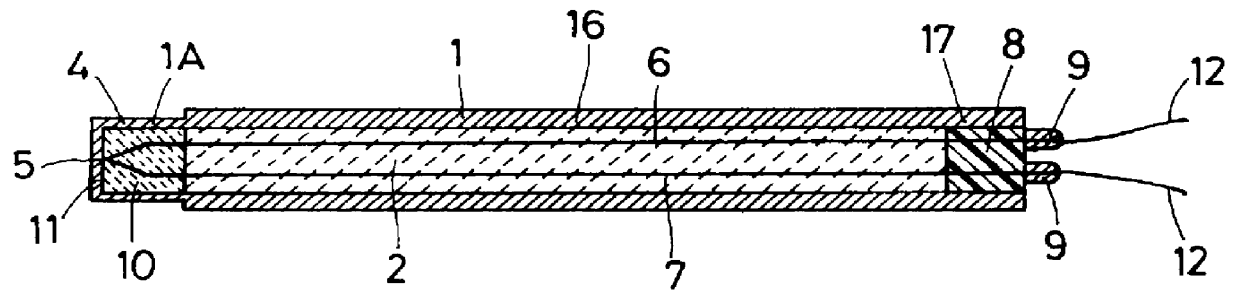
The first embodiment of the ceramic sheath type thermocouple is manufactured as shown in FIG. 1. The protective tube 1 is formed of sialon with dimensions, 5 mm in inner diameter, 8 mm in outer diameter and 300 mm in length. As to the geometry of the protective tube 1, the front end 11 of the front end portion 4 is hermetically closed while the rear end of the rear portion 16 is open. The W--Re wires 6, 7 comprise a 0.5-mm-diameter W--Re wire 6 made of W-5%Re(+) and a 0.5-mm-diameter W--Re wire 7 made of W-26%Re(-), serially connected together at one end. The joint portion of the connected wires is situated in a region of the temperature measuring point 5 of the protective tube 1 in such a way that it remains out of contact with the protective tube 1. Next, a slurry (to be transformed into the filler 2) containing a mixture of 40% Si powder by weight, 50% Si.sub.3 N.sub.4 by weight and 10% Ti by weight is filled into the front end portion 4 of the protective tube 1 up to 15 mm from ...
embodiment 2
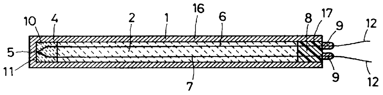
The ceramic sheath type thermocouple of the second embodiment is fabricated as shown in FIG. 2. The second embodiment uses the protective tube 1 and W--Re wires 6, 7, both similar to those of the first embodiment. It loads a slurry (to be transformed into the filler 10) containing a mixture of 40% Si powder by weight, 50% AlN by weight and 10% Ti by weight into the front end portion 4 of the protective tube 1 up to 15 mm from the front end 11 and also a slurry (to be transformed into the filler 2) containing a mixture of 40% Si powder by weight, 50% Si.sub.3 N.sub.4 by weight and 10% Ti by weight into the rear portion 16 of the protective tube 1. From this point afterward, the second embodiment is manufactured in a manner similar to the first embodiment.
The filler 10, the slurry loaded into the front end portion 4 of the protective tube 1, is transformed into an Si.sub.3 N.sub.4 reaction-sintered ceramics, a composite ceramics, with a heat conductivity .lambda. of 15 W / m.multidot.K....
embodiment 3
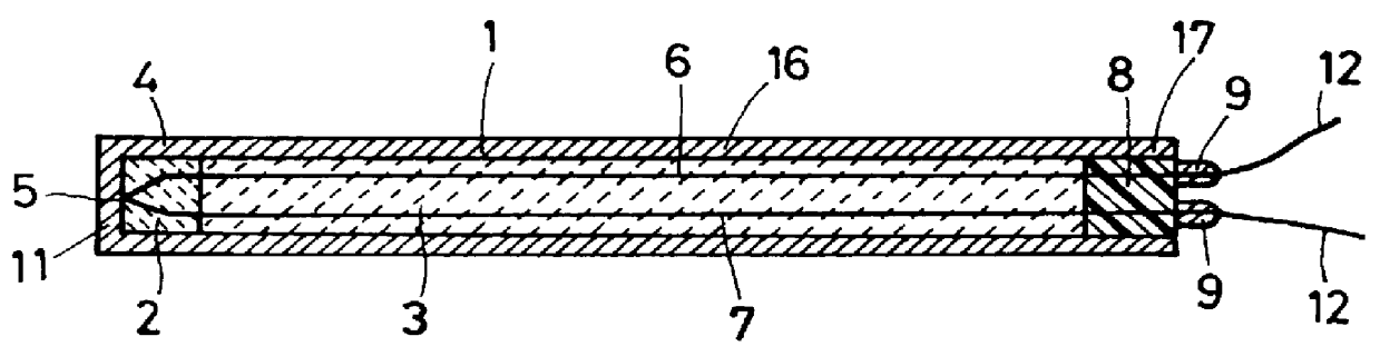
The ceramic sheath type thermocouple of the third embodiment is manufactured as shown in FIG. 3. The third embodiment uses the W--Re wires 6, 7 and fillers 2, 3, both similar to those of the first embodiment. The front end portion 4 of the protective tube 1 extending rearwardly up to 15 mm from the front end is formed as a 6-mm-outer-diameter thin tube portion 1A of sialon with the same inner diameter and length as those the protective tube 1 of the first embodiment, i.e., 5 mm in inner diameter and 300 mm long. The third embodiment is thereafter manufactured in the same process as the first embodiment.
The third embodiment uses for the fillers 2 of the front end portion 4 of the protective tube 1 and for the filler 3 of the rear portion 16 the same materials as those used in the first embodiment. Hence, the only difference between the first and the third embodiment is the thickness of the front end portion 4 of the protective tube 1 This product is taken as an item 3 of this inventi...
PUM
| Property | Measurement | Unit |
|---|---|---|
| temperatures | aaaaa | aaaaa |
| temperatures | aaaaa | aaaaa |
| temperatures | aaaaa | aaaaa |
Abstract
Description
Claims
Application Information