

Polymerization process using separated flow
a technology of polymerization and flow, applied in chemical/physical/physical-chemical stationary reactors, chemical/physical processes, pressure vessels for chemical processes, etc., can solve the problems of frequent restrictions, inability to form fluidized beds, and large stirring energy, and achieve small power energy, excellent thermal efficiency, and the effect of greatly simplifying the equipment for drying the resulting polymer
- Summary
- Abstract
- Description
- Claims
- Application Information
AI Technical Summary
Benefits of technology
Problems solved by technology
Method used
Image

Examples
example 1
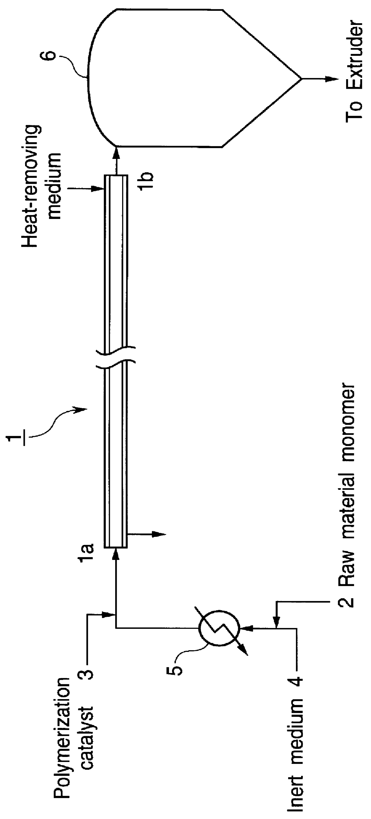
To a tubular reactor (steel tube of 1 / 2B.times.40 m) were fed raw material monomers, i.e., ethylene and an .alpha.-olefin of 6 carbon atoms (4-methyl-1-pentene), a Ziegler type titanium prepolymerized catalyst (containing 2,000 g of prepolymerized ethylene per 1 g of a transition metal compound catalyst component), an alkylaluminum and n-decane, to copolymerize the raw material monomers under the following conditions.
Ethylene / .alpha.-olefin / n-decane: 83 / 11 / 6 (by mol)
Gas linear velocity (inlet of reactor): 30 m / sec
Reaction temperature: 170.degree. C.
Reaction pressure: 16 kg / cm.sup.2.F
S / G ratio (volume flow rate ratio): 1.3.times.10.sup.-3
S / G ratio (mass flow rate ratio): 0.05
Concentration of liquid phase (polymer liquid) (outlet of reactor): 80% by weight
Viscosity of liquid phase (polymer liquid) (outlet of reactor): 1,000 poise
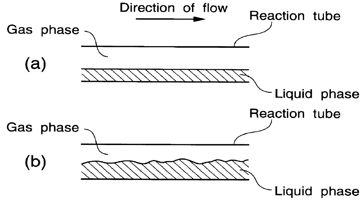
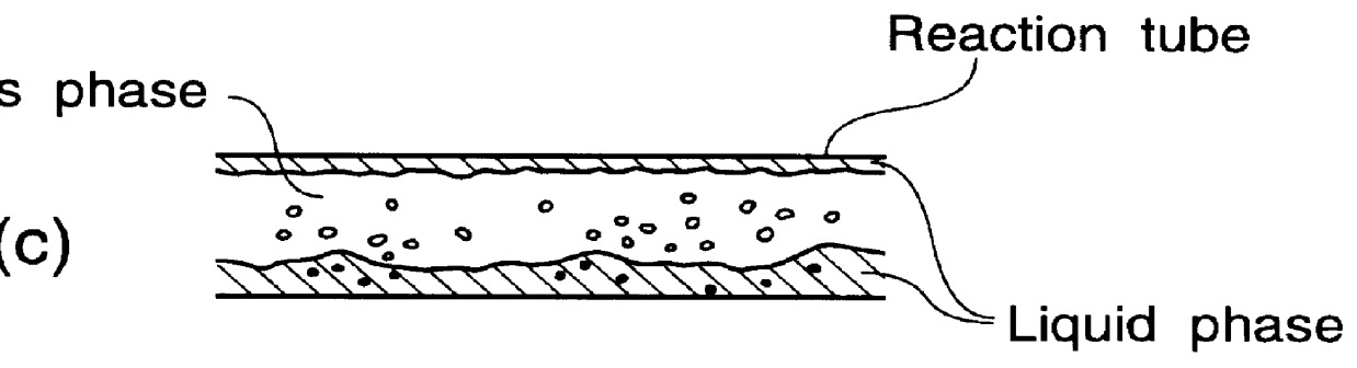
In the above polymerization, a gas-liquid separated flow was formed in the reaction tube.
Through the above polymerization, high-quality polyethylene was obtai...
example 2
Polymerization was carried out in the same manner as in Example 1, except that the polymerization conditions were varied to the following conditions.
Ethylene / .alpha.-olefin / n-decane: 71 / 22 / 6 (by mol)
Gas linear velocity (inlet of reactor): 5 m / sec
Reaction temperature: 155.degree. C.
Reaction pressure: 11 kg / cm.sup.2.F
S / G ratio (volume flow rate ratio): 1.0.times.10.sup.-4
S / G ratio (mass flow rate ratio): 0.005
Concentration of liquid phase (polymer liquid) (outlet of reactor): 80% by weight
Viscosity of liquid phase (polymer liquid) (outlet of reactor): 100 poise
In the above polymerization, a gas-liquid separated flow was formed in the reaction tube.
Through the above polymerization, high-quality polyethylene was obtained in an amount of 400,000 g per 1 g of the transition metal compound catalyst component and at a flow rate of 0.1 kg / hr at the outlet of the reactor.
The resulting polyethylene had a MI of 35 g / 10 min and a density of 0.89 g / cm.sup.3.
In the above polymerization process, th...
example 3
To a tubular reactor (steel tube of 1 / 2B.times.25 m+5 / 6B.times.15 m) were fed a raw material monomer (ethylene), the same prepolymerized catalyst as used in Example 1, an alkylaluminum and n-decane, to polymerize the raw material monomer under the following conditions.
Ethylene / n-decane: 81 / 19 (by mol)
Gas linear velocity (inlet of reactor): 15 m / sec
Reaction temperature: 160.degree. C.
Reaction pressure: 8 kg / cm.sup.2.F
S / G ratio (volume flow rate ratio): 3.5.times.10.sup.-5
S / G ratio (mass flow rate ratio): 0.0035
Concentration of liquid phase (polymer liquid) (outlet of reactor): 80% by weight
Viscosity of liquid phase (polymer liquid) (outlet of reactor): 500 poise
In the above polymerization, a gas-liquid separated flow was formed in the reaction tube.
Through the above polymerization, polyethylene was obtained in an amount of 146,000 g per 1 g of the transition metal compound catalyst component at the outlet of the reactor.
The resulting polyethylene had a MI of 1.0 g / 10 min and a densit...
PUM
| Property | Measurement | Unit |
|---|---|---|
| particle diameter | aaaaa | aaaaa |
| boiling point | aaaaa | aaaaa |
| boiling point | aaaaa | aaaaa |
Abstract
Description
Claims
Application Information