Ink-jet recording head with piezoelectric device and method for manufacturing the same

a piezoelectric device and recording head technology, applied in the field of inkjet recording head, can solve the problem of difficult to obtain a single piezoelectric ceramic composition having a satisfactory piezoelectric constant d, and achieve the effect of increasing the piezoelectric constant, increasing the drive voltage, and increasing the number of fabrication steps

Inactive Publication Date: 2000-11-07
SEIKO EPSON CORP
View PDF4 Cites 344 Cited by
  • Summary
  • Abstract
  • Description
  • Claims
  • Application Information

AI Technical Summary

Benefits of technology

ive voltage will be raised and the advantage of the present invention will be lost. When there are too few layers laminated, the uniformity of the compositions due to the diffusion phenomenon is accelerated between the two piezoelectric layers, so that the resultant structure of the piezoelectric device would be the same as that consisting of a single composition, and an increase in the piezoelectric constant d could not be expected. Further, if each ceramic layer is too thick, the thickness of the entire layer lamination is increased accordingly, and a higher drive voltage will be required. On the contrary, if each ceramic layer is formed too thin, the thicknesses of the layers will not be uniform, so that the characteristics of the individual piezoelectric devices that are separated by etching will be varied, the number of fabrication steps will be increased and the manufacturing costs will be raised. Thus, preferably, two to six ceramic layers are laminated for each piezoelectric layer, and more preferably, four layers. It is preferable that the thickness of each ceramic layer be 80 nm to 200 nm, and more preferably, 125 nm.
The ceramic layers constituting each piezoelectric layer need not have the same thickness. For example, only layers (414 and 424) that contact other compositions may be formed thin; the other layers may be thick. In this manner, the thickness of the layer through which the diffusion of compositions will occur can be reduced.
The lower electrode film 30 is paired with the upper electrode film 40 to apply a voltage to the piezoelectric layers, and is formed by laminating conductive materials, such as a titanium (Ti) layer 301, a platinum (Pt) layer 302 and a titanium (Ti) layer 303. Further, in order to improve the contact between the lower electrode film 30, which includes the titanium layer 301, the platinum layer 302 and the titanium layer 303, and the insulating film 31, a titanium oxide layer 304 and a titanium layer 305 are inserted between the lower electrode film 30 and the insulating film 31.
The insulating film 31 is made of non-conductive material, such as silicon dioxide, which is formed by thermal oxidation of a silicon substrate. The insulating film 31 can be deformed, as the piezoelectric layer is displaced in the direction of thickness and the perpendicular direction, and momentarily increases the pressure inside the cavities 21.
A piezoelectric constant d is provided as an index for the characteristic of a piezoelectric device, and is represented by the unit C / N, i.e., by the quantity of electric charges that are generated upon the application of a pressure of 1 newton. The piezoelectric constant d correlates with a product of piezoelectric constant g, which is a factor of proportionality derived from an electric field and stress, and a dielectric constant, which is a factor of proportionality derived from an electric field and a face charge density.
When laminated ceramic layers are a piezoelectric layer that has the first piezoelectric constant g1 and the first dielectric constant .di-elect cons..sub.1, and a piezoelectric layer that has the second piezoelectric constant g.sub.2 (g.sub.1 <g.sub.2) and the second dielectric constant .di-elect cons..sub.2 (.di-elect cons..sub.1 >.di-elect cons..sub.2), the piezoelectric constant d in the direction of the thickness of the two layers is represented as:

Problems solved by technology

However, when an experiment is conducted while changing the composition of a piezoelectric ceramic material used to form a piezoelectric device in order to obtain the desired characteristic for an ink-jet recording head, it is difficult to obtain a single piezoelectric ceramic composition having a satisfactory piezoelectric constant d.

Method used


Image

  • Ink-jet recording head with piezoelectric device and method for manufacturing the same
  • Ink-jet recording head with piezoelectric device and method for manufacturing the same
  • Ink-jet recording head with piezoelectric device and method for manufacturing the same

Examples


example 1

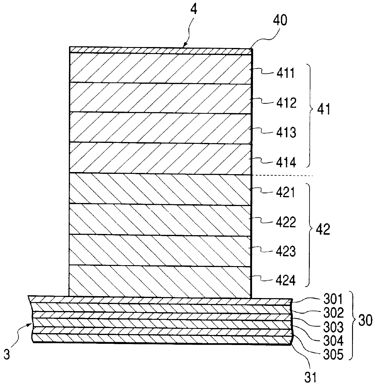
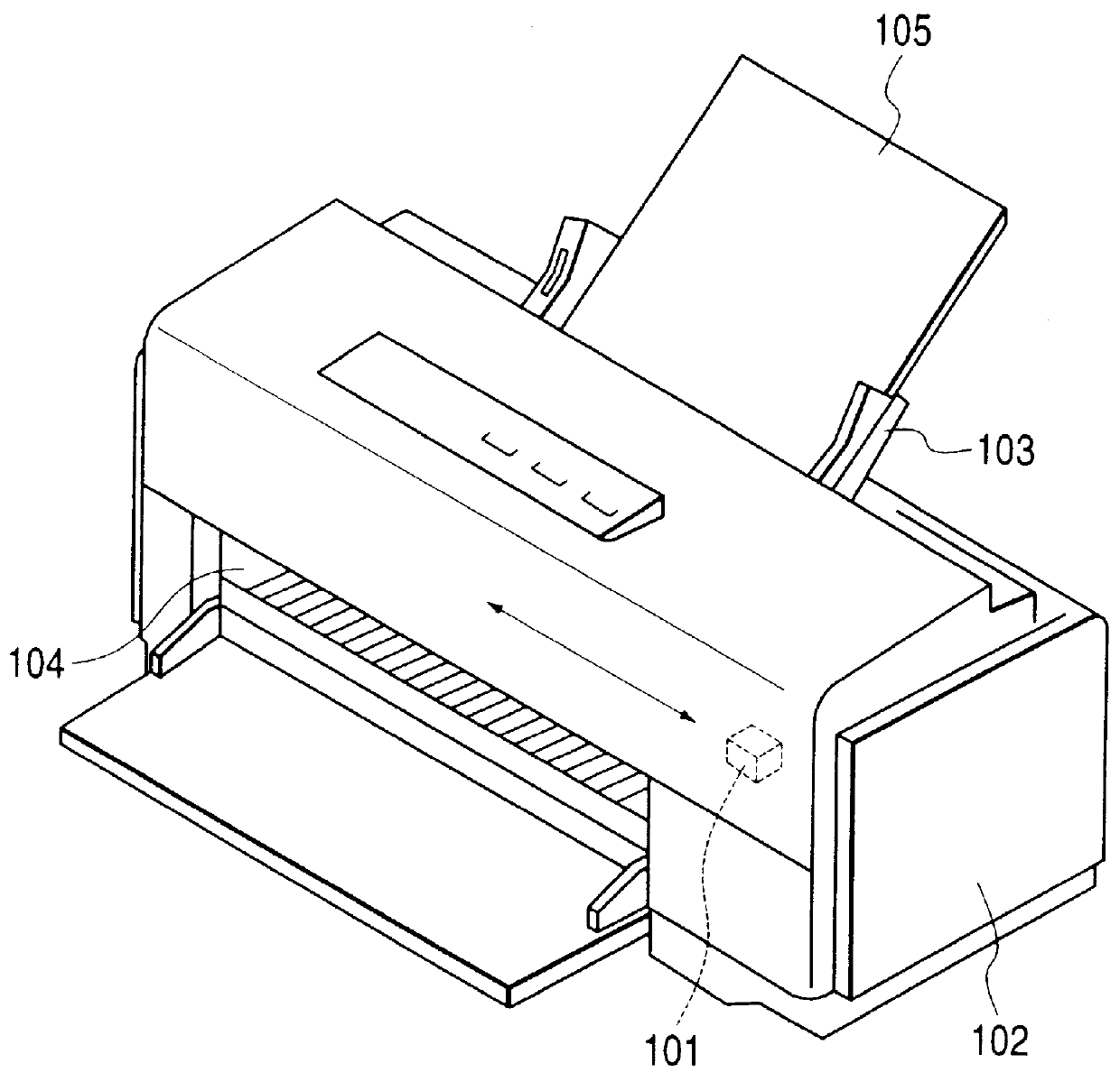
The ink-jet recording head 101 was acquired by employing the above described manufacturing method. Pb(Zr.sub.0.56 Ti.sub.0.44).sub.0.8 (Mg.sub.1 / 3 Nb.sub.2 / 3).sub.0.2 O.sub.3 was employed as the composition for the first piezoelectric layer, and PbZr.sub.0.56 Ti.sub.0.44 O.sub.3 was employed as the composition for the second piezoelectric layer. When the number of ions of individual elements (Pb, Zr, Ti, Mg, Nb, O, Pt and Si) were measured relative to the piezoelectric layer depth of the ink-jet recording head in this example, they were changed as is shown in FIG. 7.

As is shown in FIG. 7, the magnesium Mg content and the niobium Nb content of the first piezoelectric layer are increased compared with those of the second piezoelectric layer. It is understood that ion diffusion was protected and the original compositions of the two piezoelectric layers were maintained. This is because each piezoelectric layer is constituted by four layers. The thickness of the first piezoelectric layer...

example 2

In Example 2 of the present invention, the effect of Mg on the first piezoelectric layer was examined. Table 2 shows the piezoelectric characteristic, as well as the voltage withstandability and the durability, of a piezoelectric device that is formed with a material having the composition shown in equations (1) and (2), instead of the composition used for the first piezoelectric layer in example 1. The piezoelectric characteristic of a piezoelectric device that is formed as a single layer is also shown for the comparison.

As is apparent from Table 2, when Mg is not present in the first piezoelectric layer, the piezoelectric characteristic d of the total device is increased and the voltage withstandability and the durability are also superior.

embodiment 1

, a large piezoelectric constant d can be obtained by laminating a plurality of types of piezoelectric layers, and a piezoelectric device can be produced that can be displaced more than in the conventional case upon the application of the same voltage. Therefore, an ink-jet recording head can be provided that, upon the application of the same voltage, can eject a larger quantity of ink droplets at a higher speed than is possible in the conventional case.

Since each ceramic layer of the piezoelectric layer is crystallized, a diffusion phenomenon can be prevented, even for an amorphous ceramic material, and a layer structure that can maintain a large piezoelectric constant d can be provided.

The dielectric constant of the piezoelectric device as a whole can be increased by using a specific composition for one of piezoelectric layers. Especially when a composition that does not include Mg is employed for a piezoelectric layer, a piezoelectric device can be provided that has superior volt...


PUM

PropertyMeasurementUnit
thickaaaaaaaaaa
thicknessaaaaaaaaaa
thicknessaaaaaaaaaa

Abstract

A piezoelectric device for an ink jet print head that has a greater displacement at a low drive voltage. The ink-jet recording head includes a vibration plate, on which is mounted one or more piezoelectric devices that change the volumes of pressure chambers upon application of a voltage. The device is mounted at least on one face of a pressure chamber substrate that is to be filled with ink. Such piezoelectric device includes a second piezoelectric layer having a piezoelectric constant g of a constant value or higher; and a first piezoelectric layer having a dielectric constant of a specific value or higher. Since the piezoelectric constant d of the piezoelectric device correlates with the product of the largest piezoelectric constant g and the largest dielectric device of the piezoelectric devices, a piezoelectric constant d larger than in the conventional case, i.e., having a greater displacement, can be obtained.

Description

The present invention relates to an ink-jet recording head operative to eject ink droplets through nozzles to perform printing on a recording medium, and in particular to an ink-jet recording head that includes a piezoelectric layer that can generate greater pressure in a pressure chamber in which ink is retained. The present invention also relates to a fabrication method for such ink jet recording head with a piezoelectric layer.DESCRIPTION OF THE BACKGROUND ARTIn an ink-jet recording head, a voltage applied to a piezoelectric device formed on a vibration plate causes a momentary change in the volume of a pressure chamber that communicates with nozzles and increases the pressure therein. The increased pressure causes ink droplets to be ejected from the nozzles and onto a recording medium.For a conventional ink-jet printer, a piezoelectric ceramic layer made of lead zirconate titanate (PZT), for example, is formed on one face of a pressure chamber substrate to provide a piezoelectri...

Claims


Application Information

Patent Timeline
Patent Type & Authority Patents(United States)
IPC IPC(8): B41J2/14B41J2/16H01L41/18H01L41/187H01L41/09B41J2/045B41J2/055B41J2/135C04B35/49C04B35/493H01L41/318H01L41/39
CPCB41J2/14233B41J2/161B41J2/1628B41J2/1645H01L41/0973H01L41/187B41J2/1646B41J2002/14258B41J2002/14387H10N30/2047H10N30/853
Inventor QIU, HONGMORIYA, SOICHIKAMEI, HIROYUKISUMI, KOJI
Owner SEIKO EPSON CORP
Why Eureka
Try Eureka