Optical scanning with phase shifted beam

Inactive Publication Date: 2000-11-07
BINDING SOLUTIONS +1
View PDF17 Cites 15 Cited by
  • Summary
  • Abstract
  • Description
  • Claims
  • Application Information

AI Technical Summary

Benefits of technology

It is an object of the present invention to provide a multi-beam scanning system which

Problems solved by technology

A wobble, for example in the spinning dove prism of the '528 patent or degradation in performance due to wear in moving components of the support structure, will cause a misalignment of the element with respect to the spin deflector and can create significant banding artifacts in the scan lines which repeat every two scan passes.
However, alignment errors, can also create a twinning between groups of the multiple beams.
Any synchronization errors between the redirection of the redirected beam(s) and the angular position of the spin deflector will make it impossible to obtain a proper scan of t

Method used


Image

  • Optical scanning with phase shifted beam
  • Optical scanning with phase shifted beam
  • Optical scanning with phase shifted beam

Examples


first embodiment

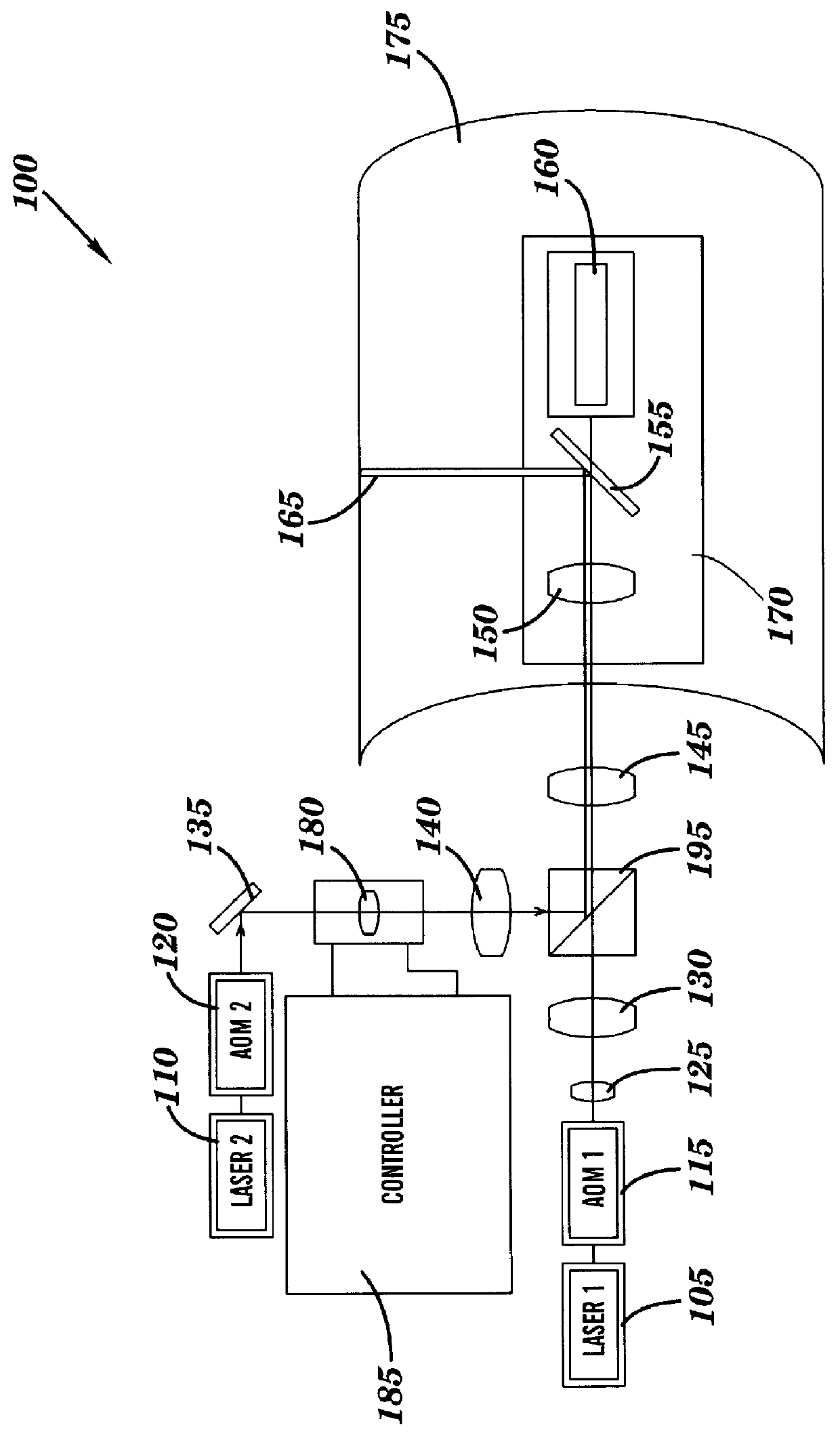
FIG. 1 depicts a multi-beam scanning system 100 with a beam deflecting lens element in accordance with the present invention. As depicted, the system includes a first laser 105 which generates a laser light beam directed on a first path to the acoustic-optic modulator (AOM) 115 which modulates the first beam before it passes through focusing lens 125 and collimating lens 130. The beam is directed substantially along the longitudinal axis of the cylindrical drum 175 which is substantially coincident with the spin axis of spin mirror 155. After collimating, the beam is directed to the beam combiner 195.

Also depicted is a second laser light generator 110 which generates a laser light beam and directs the beam on a second path through acousto-optic modulator 120 which independently modulates the second beam. The beam is then reflected off stationary mirror 135 to beam deflector lens 180 which is controlled by controller 185 to translate in two directions simultaneously thereby redirecti...

ninth embodiment

FIG. 11 depicts a multi-beam scanning system 1300". The system is similar to that depicted in FIGS. 6 and 8 and accordingly like elements are identified with like reference numerals. The scanning system 1300", however, does not include a beam deflecting lens or a beam deflecting AOM which is external to the beam generation module. As indicated in FIG. 12 which details the BGM 1310", the AOMs 1420" and 1455" are each controlled by the controller / phase shifter 1395" and are associated with pixel clocks 1512A" and 1512B", respectively, which are operated such that the AOMS 1420" and 1455" deflect and phase shift the respective beams emitted from the BGM 1310" so as to be phase aligned and redirected to linearly scan the spin mirror 1330" and in synchrony with the rotation thereof. It should be noted that AOM 1420" and AOM 1455" simultaneously modulate and deflect the beams. Further, preferably the beams are deflected so as to impinge upon the spin mirror 1330" at an equal distance from...

tenth embodiment

Turning now to FIGS. 13 and 14. a multi-beam scanning system 1300'" is depicted. System 1300'" is similar to the systems depicted in FIG. 6 and particularly FIG. 8. In system 1300'", two AOMs 1455'" and 1575' are utilized to deflect one of the beams in two directions to cause the beam to be redirected to move about the spin axis of the spin mirror 1330 and in synchrony therewith. Both AOMs 1455'" and 1575' are controlled by the controller 1395'" in the same manner as has been discussed above, the respective AOMs being controlled to deflect each the beam in different orthogonal directions.

As described above, the present invention provides a multi-beam scanning system which does not require a spin or wobble element to rotate one or more of the multiple beams. The described scanning systems has reduced banding and / or twinning. The scanning systems are capable of scanning multiple beams having a desired geometric relationship with respect to each other. The scanning systems also can sca...


PUM


Abstract

A beam scanning system for scanning an imaging surface includes a phase shifter for issuing phase signals, a radiation emitter for emitting a beam of radiation and a deflection element, such as an acousto-optic modulator or translating lens, for deflecting the radiation beam. Depending on the implementation, the emitter can be configured to phase shift the radiation beam and/or the deflection element can be configured to deflect the radiation beam in accordance with the issued phase signals. By emitting and/or deflecting the radiation beam in accordance with the phase signals, the length of the scan line formed on the imaging surface can be controlled. A deflector, such as a spin mirror or rotatable prism, is provided to direct the radiation beam to form a scan line on the imaging surface.

Description

This application is related to application Ser. No. 08 / 706,339, entitled "MULTI-BEAM SCANNER WITH MECHANICALLY MOVING ELEMENT FOR SCANNING IMAGING SURFACES", now U.S. Pat. No. 5,864,418.This application is also related to application Ser. No. 08 / 687,931, entitled "BEAM ERROR CORRECTION USING MOVABLE CORRECTION ELEMENT", filed on Jul. 29, 1996, now U.S. Pat. No. 5,877,494 and to application Ser. No. 08 / 687,928, entitled "BEAM ALIGNMENT CORRECTION ELEMENT ASSEMBLY", filed on Jul. 29, 1996, now U.S. Pat. No. 5,909,323.1. Technical FieldThe present invention relates to beam scanning systems and more particularly to multi-beam scanning systems with an acousto-optic element for deflecting a beam in one or two directions to scan imaging surfaces such as those utilized in electronic prepress operations.2. Background ArtModern electronic prepress operations utilize laser scanning systems to write or record images for subsequent reproduction or to scan a prerecorded image at a predefined reso...

Claims


Application Information

Patent Timeline
IPC IPC(8): B41J2/47B41J2/435G02B26/10H04N1/047H04N1/053H04N1/06B41B19/00H04N1/191
CPCB41B19/00B41J2/473G02B26/10H04N1/047H04N1/053H04N1/0635H04N1/1911H04N2201/04786H04N2201/04765H04N1/0607H04N2201/0471H04N2201/0476H04N2201/04732H04N2201/04744H04N2201/04734H04N2201/02439H04N2201/04794
Inventor ALLEN, ROY D.SCHOLTEN, FRANK
Owner BINDING SOLUTIONS
Why Eureka
Try Eureka