Immersible seismic emission device and implementation method

a technology of emission device and emission source, which is applied in the direction of seismic signal recording, measurement device, instruments, etc., can solve the problems of not being able to repeat exactly the same geometry of emission-reception system, it is faster and obviously much more expensive to use several workboats, and the prospecting method using towed immersed sources suffers from a common drawback

Inactive Publication Date: 2001-01-16
INST FR DU PETROLE
View PDF8 Cites 48 Cited by
  • Summary
  • Abstract
  • Description
  • Claims
  • Application Information

AI Technical Summary

Problems solved by technology

It is faster and obviously much more expensive to use several workboats each towing a marine source and to trigger them in sequence for each position of the logging tool.
Prospecting methods using towed immersed sources suffer from a common drawback.
In fact, it is not possible to repeat exactly the same geometry of the emission-reception system from one exploration session to the next notably bec

Method used


Image

  • Immersible seismic emission device and implementation method
  • Immersible seismic emission device and implementation method
  • Immersible seismic emission device and implementation method

Examples


Embodiment Construction

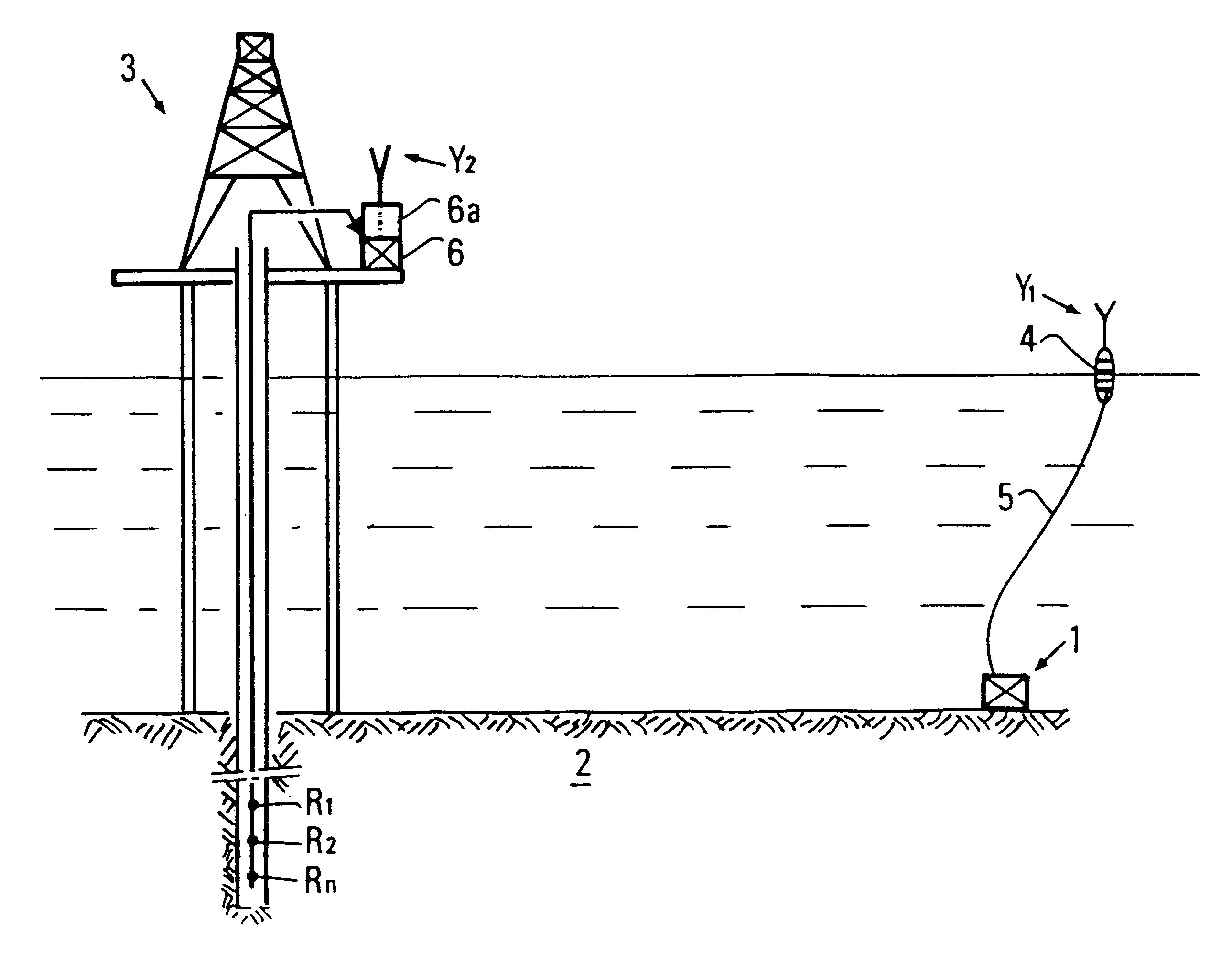
A device in accordance with the invention comprises one or more emission units 1 placed in contact with an underwater formation 2 to be explored, such as a reservoir containing hydrocarbons for example. This emission unit 1 is positioned on the bottom in a zone surrounding a development station such as a drilling or a production platform 3, above a well drilled through formation 2. A set of seismic receivers R1, R2, . . . , Rn, such as multi-axis geophones for example and / or accelerometers and / or hydrophones, is lowered in this well.

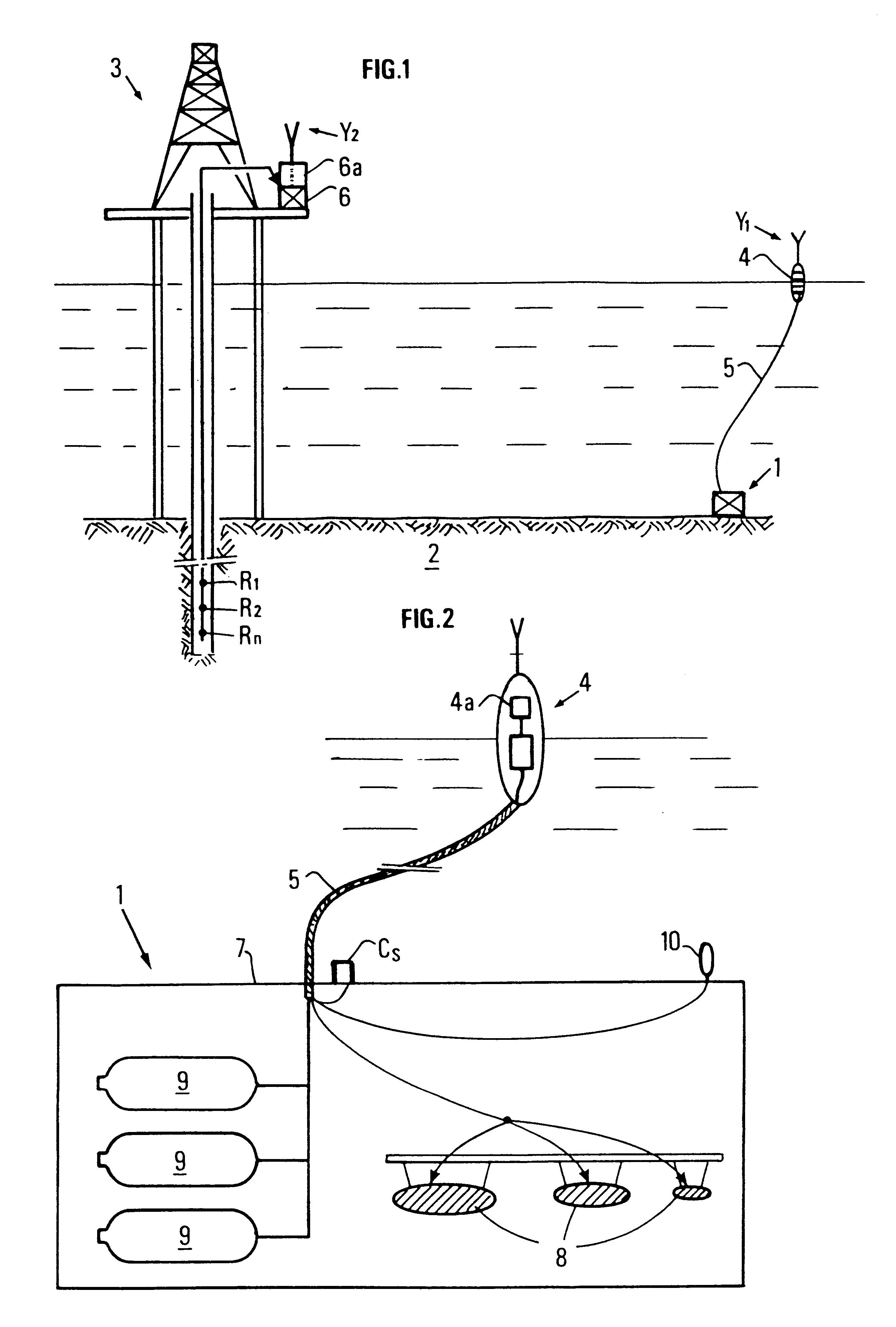
Each emission unit is connected to a surface buoy 4 by a multifunction cable 5. A transmission system connects each buoy 4 to a control station 6 on surface installation 3. This system comprises two modules, the first one 6a being placed in control station 6, the second module 4a being placed in each buoy 4 and communicating with the first one by radio link by means of antennas Y1, Y2 for example.

Each emission unit 1 comprises (FIG. 2) a rigid frame 7 su...


PUM


Abstract

The invention is a seismic emission device designed to be immersed at the bottom of a water body (sea, lake, etc.), and method of implementation. The device comprises at least one (and preferably several) self-contained emission units (1) immersible at the bottom of a water body, combining at least one or more seismic wave sources (8), such as air guns for example, suited to be placed in contact with the body, local energy storage (9) which supplies the device a multifunction connection cable (5) connecting each self-contained emission unit to a surface relay unit (4), a communication system (4a, 6a, Y) providing communication with a central control station (6) located for example on a drilling or production platform (3). VSP repetitive exploration operations can be carried out in a well by activating successively the various emission units and by acquiring the signals picked up by receivers R1-n placed in a well for example and coupled with the formation. The device can be used for oil prospecting.

Description

1. Field of the InventionThe present invention relates to a method and to a device for carrying out operations of seismic monitoring of an underwater zone by means of elastic wave sources permanently installed against the bottom of the water mass.2. Description of the Prior ArtDuring production of a reservoir, it is well-known to carry out cyclic seismic exploration operations with transmission in the formation of elastic waves, recording of the waves reflected by the subsoil discontinuities and processing of the acquired seismic data in order for example to follow the evolution of the reservoir with time.A conventional method referred to as VSP consists in coupling the wall of a well to a string of seismic receivers placed at intervals along a conventional logging cable in order to pick up the waves reflected by the discontinuities of the surrounding formation in response to the waves emitted by a source outside the well.In order to simplify and to accelerate these periodic seismic...

Claims


Application Information

Patent Timeline
IPC IPC(8): G01V1/26G01V1/38G01V1/00
CPCG01V1/26G01V1/3808
Inventor NAVILLE, CHARLES
Owner INST FR DU PETROLE
Why Eureka
Try Eureka