Armor coating for a metal engine component, and method of producing the same

a technology of armor coating and engine components, which is applied in the direction of machines/engines, instruments, transportation and packaging, etc., can solve the problems of forming defects, gaps or voids in the coating layer, and increasing the wear of engine components, so as to avoid the formation of defects, gaps or voids in the coating layer, and undesirable variations in the thickness of the coating layer

Inactive Publication Date: 2001-01-23
MOTOREN UND TURBINEN UNION MUNCHEN GMBH
View PDF6 Cites 17 Cited by
  • Summary
  • Abstract
  • Description
  • Claims
  • Application Information

AI Technical Summary

Benefits of technology

Thereafter, the armor coating is applied onto the profiled surface of the engine component, whereby the armor coating itself advantageously has a uniformly profiled and coated surface, without requiring the complicated use of a wire mesh or other screening mask for covering portions of the component surface. Furthermore, the present method avoids the formation of the defects that typically arise to a great extent when using such a wire mesh mask. A further advantage is that the armor coating may have deeper grooves or other depressions than can be achieved by prior art methods. In this context, the profiled surface of the armor coating can be embodied exactly as needed to provide an optimum abrasive wear with consideration of the relative motion between the engine component having the armor coating thereon and the second engine component that may have a bedding-in coating thereon.
Alternatively, in a preferred embodiment, the peaks and depressions forming the profiled surface extend at an angle relative to the above defined rotational axis, whereby a left or right spiraling knurling tool is used to form these peaks and depressions. In comparison to the above mentioned axis-parallel knurling, this spiral knurled configuration has the advantage that the depressions or grooves will receive and simultaneously move or clear away the abrasion material.
In a preferred embodiment, the armor coating is provided on an inner diameter or radially inwardly facing surface of an engine component such as a so-called FIN component, namely a seal disk for a labyrinth seal. In this application, the peaks and depressions of the profiled surface are easily formed using a standard knurling tool that has a knurled profile on its outer diameter, i.e. its outer surface. Alternatively, the armor coating may be provided without problems on the outer diameter, i.e. the radially outwardly facing surface, of engine components such as blade tips or seal tips of a blade tip shroud band.
The above objects have further been achieved in a method for providing an armor coating on a surface of a metal engine component according to the invention, including a step of forming a profiled surface by deforming the surface of the component that is to be armor coated, and then a step of coating the profiled surface of the component with a layer of ceramic material. The advantage of this method is that the prior profiling step makes it possible to avoid the formation of defects in the subsequently formed ceramic layer. Preferably, the profiling is carried out by knurling, so that profiled surfaces having various different forms and geometries can easily be produced by simply pressing standardized knurling tools into the corresponding component surface. It is further advantageous if the armor coating of the previously profiled component surface is achieved by thermally spraying a ceramic material thereon. It can also be advantageous if the method involves a further step of finish turning the component, for example if the profiling step causes a deformation of the base material of the engine component as a result of the cold working compression thereof.

Problems solved by technology

However, if the strength and hardness of the bedding-in coating is increased in order to increase the erosion and temperature resistance thereof, then the abrasive wear of the engine components will also be increased, so that it is necessary to provide an armor coating thereon.
First, it has been found that the wire mesh completely covers the component surface or completely blocks the spray application at certain locations and thereby causes the formation of defects, gaps or voids in the coating layer.
This also causes undesirable variations in the coating layer thickness, and makes it impossible to achieve a uniform surface profiling over the entire circumference of the component.
Furthermore, the known process requires a complicated preparation of the component surface as well as handling of the wire mesh, and involves difficulties in maintaining the required spraying stream angle and limiting that angle to the range specified by the known process.

Method used


Image

  • Armor coating for a metal engine component, and method of producing the same
  • Armor coating for a metal engine component, and method of producing the same
  • Armor coating for a metal engine component, and method of producing the same

Examples


Embodiment Construction

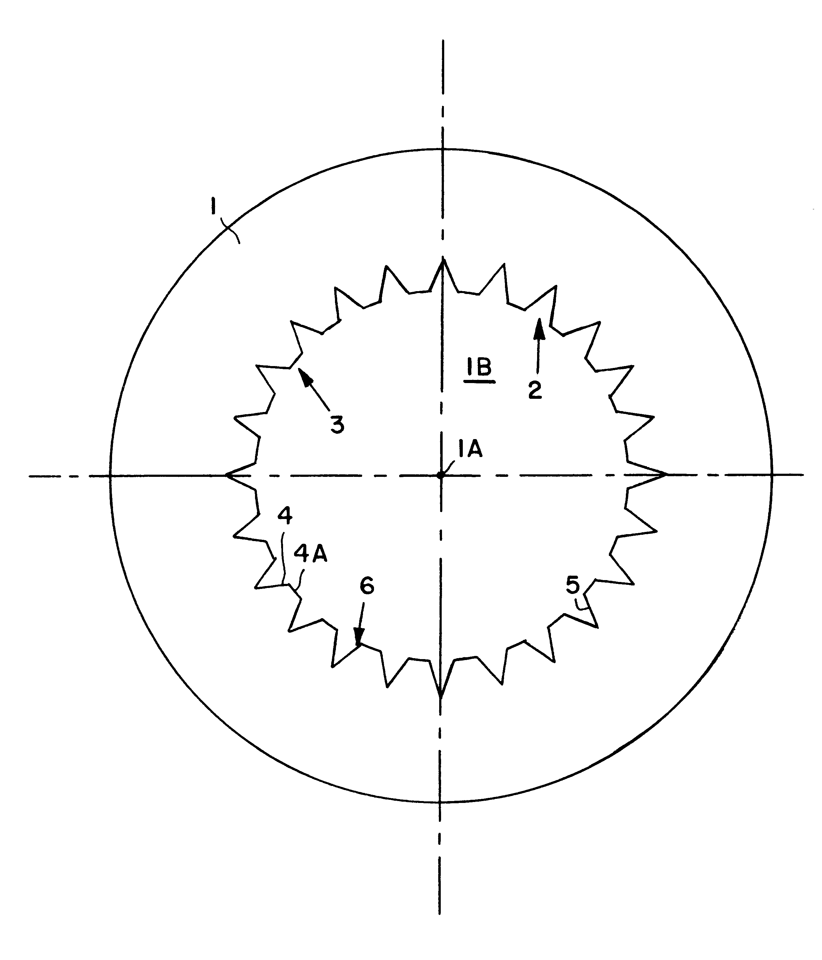
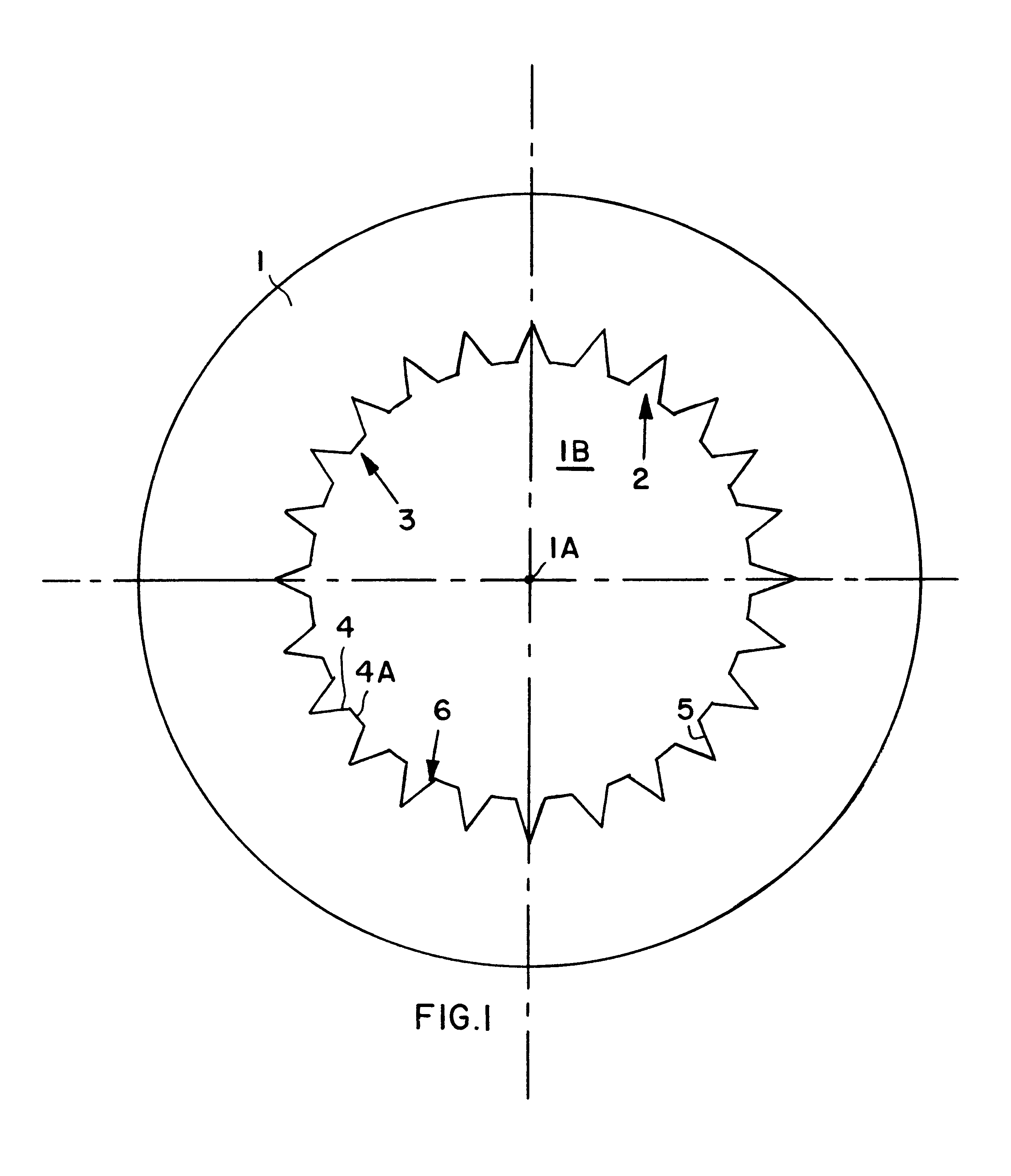
FIG. 1 is a schematic plan view of a running disk or seal disk 1 for a labyrinth seal of a jet turbine engine or the like. The seal disk 1 has an inner bore 1B bounded by an inner circumferential surface 2 with sealing tips that will form a seal in cooperation with an abradable bedding-in lining on another engine component (not shown). The seal tips are provided with an armor coating according to a first example embodiment of the invention. The armor coating 3 comprises a ceramic layer 6 that has a surface profile including peaks 4 with flat top plateaus 4A and free spaces or depressions 5 located between respective peaks 4. Generally, the ceramic layer 6 is thermally sprayed onto the previously profiled inner circumferential surface 2 of the engine component, i.e. the seal disk 1. The ceramic material for the ceramic coating 6 is Al.sub.2 O.sub.3 in the form of corundum for example.

The original or starting shape of the inner circumferential surface 2 of the seal disk 1 is a uniform...


PUM

PropertyMeasurementUnit
widthaaaaaaaaaa
depthaaaaaaaaaa
thickaaaaaaaaaa

Abstract

An armor coating (3) is provided on a surface of a metal engine component (1) that is adapted to be in grazing contact with an abradable bedding-in seal lining provided on a second engine component. The armor coating (3) includes a ceramic layer (6) and has a profiled surface contour including peaks (4, 7, 9, 10) and depressions or grooves (5) therebetween. The grooves (5) serve to receive and carry away abrasion material that is abraded from the bedding-in lining. The profiled surface contour is formed in the surface (2) of the engine component (1) by cold deformation without material removal, and thereafter the ceramic layer (6) is applied thereon preferably by thermal spraying, such that the layer (6) follows and also embodies the profiled surface contour. The cold deformation is carried out by pressing a knurling tool (11) into the original un-profiled surface (2) of the component (1).

Description

PRIORITY CLAIMThis application is based on and claims the priority under 35 U.S.C. .sctn.119 of German Patent Application 197 30 008.1, filed on Jul. 12, 1997. The entire disclosure of German Patent Application 197 30 008.1 is incorporated herein by reference.The invention relates to an anti-wear or armor coating provided on the surface of a metal engine component, which is to make grazing contact with and be abrasively bedded into a bedding-in coating or lining on a second component of the engine. The armor coating comprises a ceramic layer having alternating peaks and depressions therebetween for receiving and carrying away abrasion material. This armor coating is especially for the rotor or stator of a jet turbine engine. The invention further relates to a method of providing such an armor coating on a metal engine component.BACKGROUND INFORMATIONArmor coatings and / or abradable bedding-in linings are provided on engine components such as on the tips of sealing fins of labyrinth s...

Claims


Application Information

Patent Timeline
Patent Type & Authority Patents(United States)
IPC IPC(8): F01D11/08F01D11/12F01D25/16
CPCF01D11/125F01D25/16Y10T428/24521Y10T428/24537Y10T428/24355Y10T428/2457Y10T428/24364
Inventor LEGRAND, NORBERT
Owner MOTOREN UND TURBINEN UNION MUNCHEN GMBH
Why Eureka
Try Eureka