Ductility additives for electrorefining and electrowinning

a technology of additives and ductility, applied in the field of additives, can solve the problems of oxides which fall off during electrolysis, impurities of lead in the copper deposit, and additives commonly used tend to oxidiz

Inactive Publication Date: 2001-02-06
MACDERMID ENTHONE INC
View PDF4 Cites 28 Cited by
  • Summary
  • Abstract
  • Description
  • Claims
  • Application Information

AI Technical Summary

Problems solved by technology

This has been problematic in two respects.
First of all, additives commonly in use tend to oxidize on the insoluble lead anodes when they evolve oxygen.
This anode phenomenon also leads to lead oxides which flake off during electrolysis.
These unwanted particles will then tend to migrate to the cathodes, causing impurities of lead in the copper deposit.
These impurities lead to low ductility in these deposits.
The drawback in using this additive is that it is hard to dissolve into solution and tends to readily break down.
This creates erratic electroplating results.
This can result in sulfur co-deposition from the plating residues in the solution.
This also leaches many undesirable impurities from the ore.
If an additive is too surface active, it will interfere with the organic water separation, leading to problems.
Many organic molecules may interfere with the kinetics of the exchange reaction, reducing the efficiency thereof.
Additionally, copper selectivity over iron is somewhat sensitive in the extraction system.
This means that the circuit conductors in microchips have become thinner and thinner.
As ductility decreases, copper becomes more brittle, hindering fine formation of thin circuit leads.
Typically, in order to provide the purity and ductility necessary for such applications, it has been necessary for the electrowinned "rough" copper to be refined further, using various time consuming and expensive processes.

Method used


Image

  • Ductility additives for electrorefining and electrowinning
  • Ductility additives for electrorefining and electrowinning
  • Ductility additives for electrorefining and electrowinning

Examples


example i

An electrorefining electrolyte is analyzed and has the constituents set forth in Table I below.

TABLE I Copper Electrorefining Electrolyte Constituent Amount Copper Sulfate 180 g / l Sulfuric Acid 150 g / l Chloride Ion 30 mg / l Nickel Ion 15 mg / l Arsenic Ion 6 g / l Ferrous Ion 9 g / l Tellurium Ion 150 g / l All Other Impurities <400 mg / l

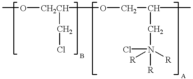
To the bath is added 11 mg / l of polyepichlorohydrin trimethylamine quarternary, having a molecular weight of 2,000 and the formula: ##STR3##

The bath is operated at 150.degree. F., at 20 amps per square foot cathode current density. The deposit is ductile and fine-grained with no dendrites.

example ii

A copper electrowinning solution is analyzed to contain the constituents set forth in Table II.

TABLE II Copper Electrowinning Electrolyte Constituent Amount Copper Sulfate 170 g / l Sulfuric Acid 165 g / l Chloride Ion 30 mg / l Nickel 7.5 mg / l Iron 9 g / l Arsenic 10 g / l All Other Impurities <500 mg / l

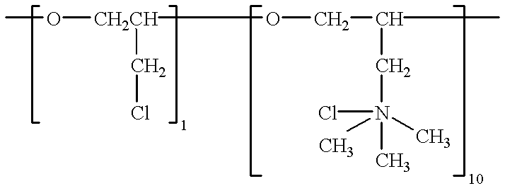
11 mg / l polyepichlorohydrin trimethylamine quarternary is added to the bath. This constituent has the formula: ##STR4##

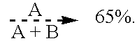
where A is about 10 and B is about 1, the compound having a molecular weight of about 2900. The bath is operated at a temperature of 140.degree. F., with cathode current densities of 12 amps per square foot. The resulting electrowinned copper is found to be pure, highly-ductile and fine-grained.

example iii

(Control)

Samples of electrowinning electrolytes were removed from a commercial electrowinning production facility, which has substantially the same chemistry as that set forth in Example I but includes glue, thiourea and avitone, and placed in one liter beakers as a comparative test. This sample is then placed in a suitable electroplating cell and heated to 150.degree. F. A copper is plated onto a passivated stainless steel substrate until a plating thickness of about 4 mils. The foil is cracked and brittle.


PUM

PropertyMeasurementUnit
concentrationaaaaaaaaaa

Abstract

A method of electrowinning, electrorefining or electroforming of ductile copper deposits. The method uses an adduct of a tertiary alkyl amine with polyepichlorohydrin in amounts effective for ductilizing a copper deposit form a copper electrolyte.

Description

BACKGROUND OF THE INVENTIONThe present invention relates to additives for producing ductile and pure copper deposits from electrowinning, electrorefining and electroforming baths. More specifically, the present invention relates to polyepichlorohydrin trimethylamine quarternary additives useful in the electrowinning, electrorefining and electroforming of copper.Electrowinning and electrorefining are methods of purifying and collecting copper for use in wire circuit boards or the like. In electrowinning, copper is plated directly from solution, using insoluble anodes such as lead. In electrorefining, the copper is plated onto a cathode from a soluble copper anode. These processes are known to those skilled in the art and have been in use since the 1800's.In electrowinning applications, it has long been desirable to provide electrodeposits which do not require further purification. This has been problematic in two respects. First of all, additives commonly in use tend to oxidize on th...

Claims


Application Information

Patent Timeline
Patent Type & Authority Patents(United States)
IPC IPC(8): C25C1/12C25C1/00
CPCC25C1/12
Inventor JANIK, ROBERT
Owner MACDERMID ENTHONE INC
Why Eureka
Try Eureka