Continuous liquid stream digital blending system

a digital blending and liquid stream technology, applied in liquid handling, instruments, packaged goods types, etc., can solve the problems of large manufacturing space, frequent change of rheological or chemical properties of batch, and many drawbacks of liquid batching, so as to reduce the volume of clean-in-place effluent, reduce loss, and reduce the effect of cip

Inactive Publication Date: 2001-02-13
ODEN MACHINERY
View PDF15 Cites 157 Cited by
  • Summary
  • Abstract
  • Description
  • Claims
  • Application Information

AI Technical Summary

Benefits of technology

It is a primary object of the present invention to overcome the numerous disadvantages, as set forth above, of presently known continuous stream liquid blending methods.
In the present invention, each liquid component flow channel is modular and consists of a high precision dosing servo-pump unit 44, 46 and an appropriately sized Coriolis mass meter 12 or 14. Together with a positive shut-off dose stream injector 18 or 20, these define a complete dosing channel apparatus. The design of several (typically seven) pre-engineered modular channel sizes allows virtually any size dose to be handled, as required by the batch formula, on a modular mix and match basis. And, the fact that each channel can be software calibrated against a precision clock frequency (established by a precision external 1 KHz clock) common to all dose channels in order to match flow rates with the other batch dose channels means that the major source of system error of previous designs, flow rate adjustments for changing ratio shifts or take-away rates, is totally eliminated. This approach also substantially simplifies the software and set-up computations required of the system. The broad dynamic range of each flow channel size (typically over 4:1) ensures that a system design can be successfully utilized across a broad range of product formulas without the need for extensive re-configurations and additions. Table 1 on the following page discloses seven typical dosing channel

Problems solved by technology

Liquids batching entails many drawbacks and limitations.
This large scale requires substantial manufacturing space, and large batch volumes dictate a relatively fixed and inflexible manufacturing schedule.
Another drawback of batching is that the batch frequently changes its rheological or chemical properties over time.
This can lead to unwanted chemical degradation and to microbial contamination.
Batching can also lead to difficulties in mixing together the liquid components in large volumes.
It is often true that the components can be mixed only with difficulty and require prolonged agitation to become homogeneous.
It is also true that the large volumes typically committed to batching cause cleaning to be slow, laborious and difficult to automate.
Large volumes of cleaning effluents are produced, leading to issues of waste and contamination.
The real issue is how to build a continuous stream blending system with the maximum degree of accuracy, flexibility of use, and versatility of application in a broad range of commercial sectors.
Several major design problems are encountered with continuous flow blending systems utilizing this flow architecture.
Also, as each stream flow rate changes it can perturb the flow rate of the other stream or streams causing hunting or oscillations.
These common control problems can cause serious loss of blended stream accuracy.
Clearly, PID loop controllers are designed to "tame" or control complex systems which are not inherently designed for stability or ease of control.
Still another problem can arise when a feedback signal change causes the flow to briefly go below or above the permissible range of the flow meter generating the feedback signal.
Perhaps the major problem encountered with these designs and the PID control architecture arises with the inevitable need to start and stop the flow stream system.
When a stop-start event occurs, it is very difficult to bring the system back on-line with balanced (that is to say accurate) flow and blending.
This problem has been so persistent that nearly all installed systems have resorted to the use of a surge tank of up to several hundred gallons capacity to allow blending flow to continue during brief filler machine stoppages.
Either method results in substantial waste, decreased blending accuracy, increased system complexity and increased system volume, thus depleting the sought after advantages of continuous stream blending.
Another major problem encountered with PID control designs occurs when blending flow rates must be altered to adjust for variable take-away demand.
The result of these inherent limitations is a lag in response to flow rate change commands, unbalance in flows during change, and overshoot of the new flow set point.
These phenomenon are inherent to PID based schemes and limit the overall performance of such systems.
While it is possible to "tune" PID controls in order to minimize dynamic control limitations and inaccuracies, in a continuous stream blending system designed to operate as a general purpose device across a wide range of blend formulas, liquid properties and flow rates, a PID loop control scheme cannot be readily optimized.
This patent does not disclose method or apparatus for combining continuously flowing multiple liquid streams on a mass ratio basis.

Method used


Image

  • Continuous liquid stream digital blending system
  • Continuous liquid stream digital blending system
  • Continuous liquid stream digital blending system

Examples


Embodiment Construction

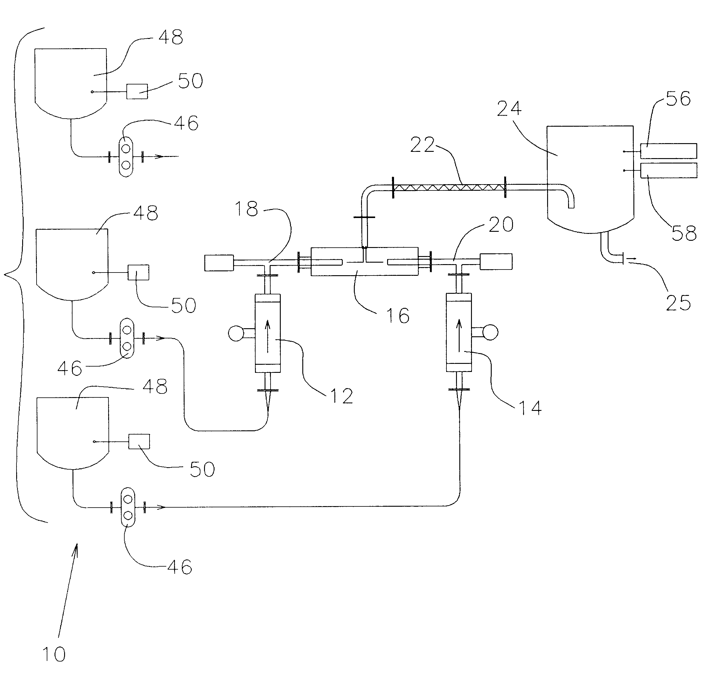
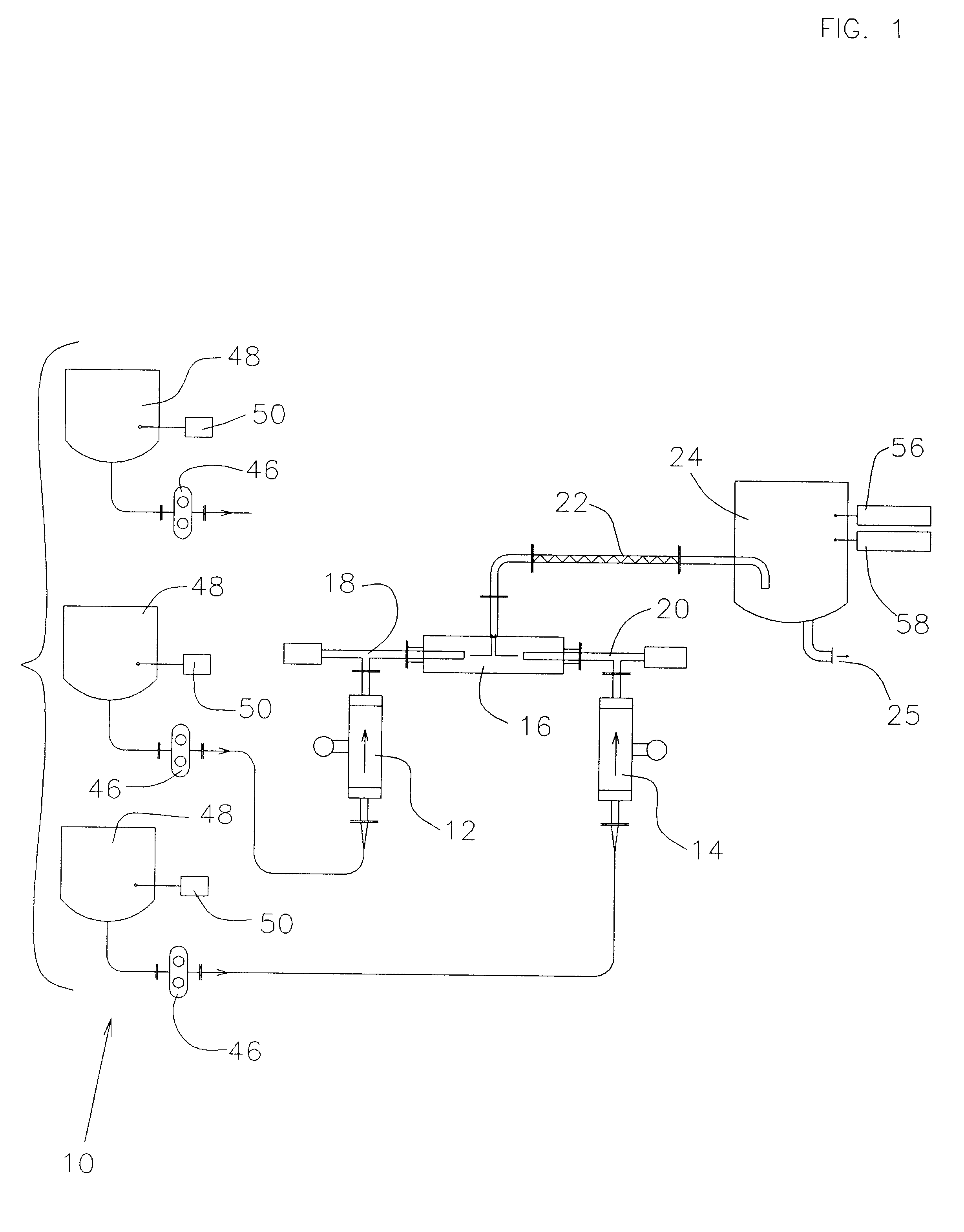
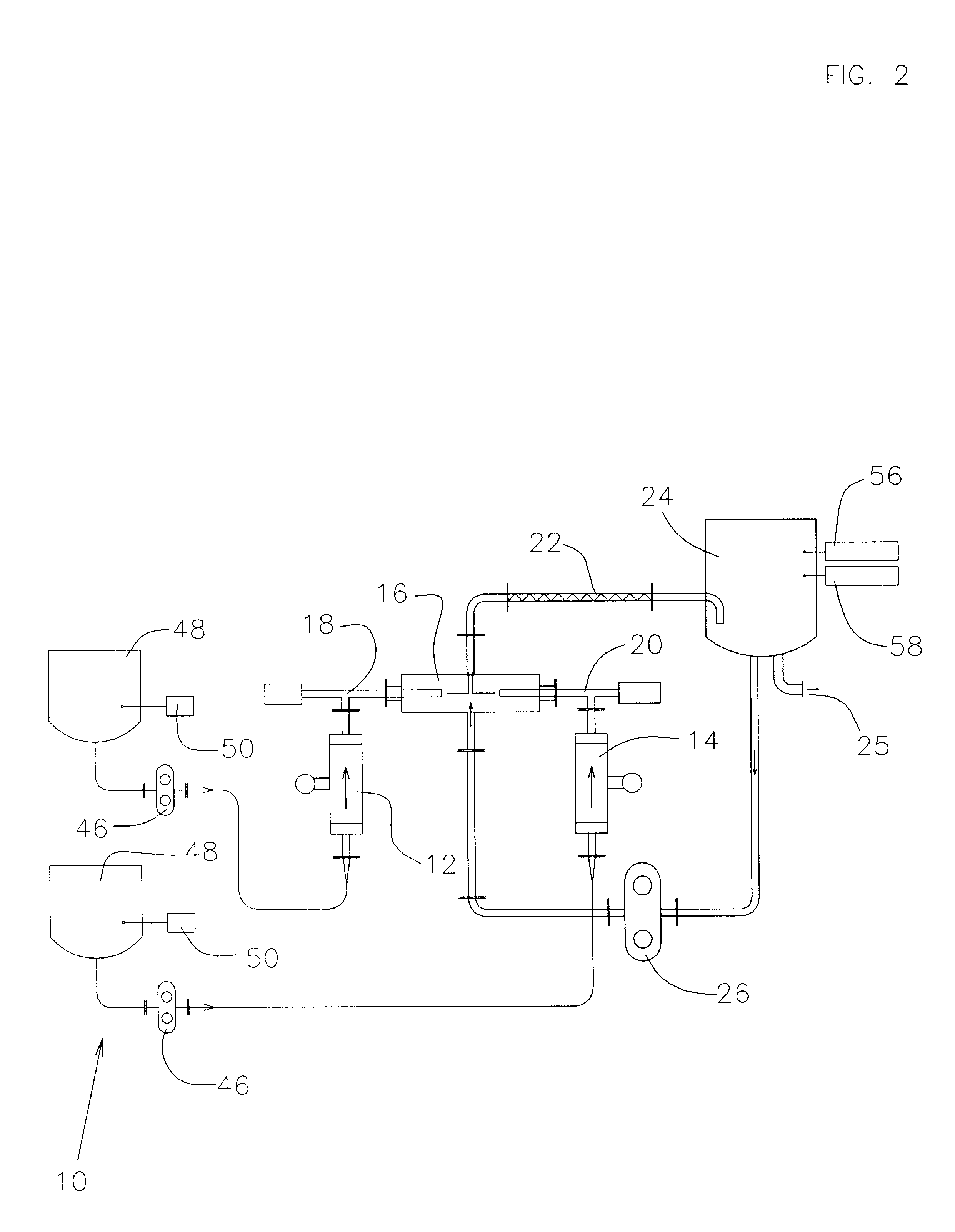
Configure a system to provide a continuous flow of liquid product to a filling line at the maximum rate of 100 GPM.

Note that the math procedures described below are actually performed in the batch computer 54, typically a high end PLC, with a color graphic active matrix LCD PC based operator interface 62.

The product formula expressed in volume ratio and units of flow per minute is:

Step 1

Convert the volumetric formula to a mass formula.

To convert the volumetric formula to mass ratio, each formula component gallon per minute volumetric ratio is multiplied by 8.3453 to convert to a water weight equivalent (in this instance in pounds). This figure is then multiplied by the specific gravity of each formula component to obtain a pounds per minute of flow number for each constituent liquid. The pounds per minute result is rounded to two decimals in this text for convenience. Thus:

Note that each flow rate of each formula component is now expressed in mass units per minute.

Step 2

Restate the ...


PUM

PropertyMeasurementUnit
duration timeaaaaaaaaaa
cycle timeaaaaaaaaaa
mass ratioaaaaaaaaaa

Abstract

The present invention consists of a method and apparatus providing for the continuous stream blending, preferably on a mass ratio basis, of two or more liquids. Each individual liquid stream is synchronously dosed in precise mass ratio to a common mixing point. The flow of each stream is on-off or digital. Repeated mass ratio doses of defined and matching flow interval, referred to as synchronous digital flow, interspersed with a defined interval of no flow, constitutes digital flow at a net rate sufficient to meet or exceed some required take-away of the blended liquids. In one preferred embodiment, each dose stream flow is produced and measured by a four element apparatus preferably consisting of a servo motor and controller, a precision positive displacement pump, a Coriolis mass meter and a precision flow stream shut-off device. The servo motor and controller establish and control a periodic and intermittent flow rate necessary to displace a defined mass dose in a precisely defined flow interval. The flow interval is measured against a precision millisecond digital clock. The Coriolis mass meter is used only to totalize mass flow to define the desired mass dose during the defined digital flow interval. The flow stream shut-off device ensures precise delivery of the mass dose to the common mixing point. The flow rate of a stream is automatically adjusted by the control electronics until the required mass dose is delivered in the defined flow interval.

Description

The present invention relates generally to a method and apparatus for the combining together of two or more liquids to form a batch or blend of desired mixture or proportions. More specifically, the invention relates to the use of intermittently operated devices for initiating liquid flow in the form of servo driven rotary positive displacement pumps, flow meters and precision flow shut-off devices to create repeated synchronized doses of two or more liquids to a common location, the string of synchronized intermittent dose cycles creating a desired net flow rate of ratio blended liquids wherein the blended flow from the apparatus can be started and stopped at will without any adverse effect upon the accuracy of the blended proportions of the liquid streams.The combining of two or more liquids together to form a defined mixture of the constituent liquids is fundamental to many industrial processes and commercial products. This combining of liquids may be referred to as batching or b...

Claims


Application Information

Patent Timeline
Patent Type & Authority Patents(United States)
IPC IPC(8): B65B3/00B65B3/30G01F1/84G01F1/76G01G17/00G01G17/04G05D11/00G05D11/13
CPCB65B3/30G01F1/84G01G17/04G05D11/132G05D11/137
Inventor PHALLEN, IVER J.JEZUIT, JR., RICHARD J.MILLETT, JR., PETER B.
Owner ODEN MACHINERY
Why Eureka
Try Eureka