Marking diamond

a diamond and diamond technology, applied in the field of diamond marking, can solve the problems of reducing the visible area of the mark, affecting the resistance of the material to irradiation, and affecting the optical quality of the cvd material, so as to avoid excessive heating of the stone, reduce the visible area, and reduce the energy consumption

Inactive Publication Date: 2001-02-13
GERSAN ESTAB
View PDF37 Cites 63 Cited by
  • Summary
  • Abstract
  • Description
  • Claims
  • Application Information

AI Technical Summary

Benefits of technology

By avoiding substantial or undesirable darkening, the visibility of the marks can be greatly reduced. As there is no undesirable darkening, there is no necessity afterwards to remove any black or grey marks (for instance by chemical processes such as acidization), which may in any case be impossible if the darkening is due to phase transformation within the diamond. As there is no requirement to remove black or grey marks, set stones can be marked. The possibility of marking set stones is also provided by the relatively low energy which can be used, avoiding excessive heating of the stone as a whole (it is believed that the rise in temperature of the stone as a whole is of the order of 0.5.degree. C. say for a 20 pt. stone (0.04 gm), though this varies according to the size of the stone and the size of the mark applied); the relatively low energy which can be used also avoids any necessity for cooling, and avoids risking damage to the stone. Thus the invention enables diamonds to be marked without forming any undesirable by-products or damaging the diamond in any other way.
The invention also enables very shallow marks to be produced in a controllable manner. The lack of substantial darkening and the shallowness enables the marks to be invisible to the eye, and they are preferably invisible to the naked eye aided with a .times.10 loupe. However, the marks can be easily visible using a microscopy technique that highlights the edges of the mark, such as dark field illumination. A metallurgical microscope can be used for such techniques. Alternatively, one can obtain an accurate three-dimensional image of the mark using an interference microscope such as the "Micromap" (trade mark) produced by Micromap of Tucson, Ariz. As there is no substantial darkening, the visibility of the mark is achieved purely by the depth of the mark. As the mark is invisible to the naked eye, it can be on the table of a good quality polished diamond (preferably in the middle or specifically in the geometric centre, where it is easy to find) without any detraction from the value of the diamond, i.e in a position which is accessible for marking and for checking when the diamond is mounted in a setting. Nonetheless, if desired, the mark could be provided on another facet, for instance on a girdle facet.

Problems solved by technology

The CVD material is often of poor optical quality and may contain significant amounts of carbon bonded in a graphite like (sp.sup.2) configuration rather than the pure diamond (sp.sup.3) configuration.
The presence of non-diamond carbon in these materials can be expected to have a detrimental effect on the resistance of the material to the irradiation.
This can lead to a build-up of a partially non-diamond layer in the irradiated region.
If a mark is produced on say the table of such a diamond that is observable with a .times.10 loupe, the clarity grade of the diamond, and hence its value, would be reduced and this would not be desirable.
Thus in addition or in the alternative undesirable darkening may be considered to be darkening that detracts from the clarity grade of the diamond.
Nonetheless, at the end of etching, a very thin modified layer may remain at the bottom of the mark, which would not be termed substantial darkening; in other words, a very thin flat modified layer as part of an information mark on a facet of a polished diamond gem may not be visible enough to be detrimental to the value of a stone, although it would be undesirable.
However, as laser scanning may be too slow in practice, a masking technique can be used, and such techniques are well known.
A preferred reagent is a fluid, preferably a gas, and the preferred gas is an oxidising gas such as air; though it is possible to use gases other than oxygen, the etching process is less effective if oxygen is excluded from the irradition zone.
The rate of the process is much too slow to be useful for processes such as sawing and the formation of structures deeper than eg 10 microns in diamond.

Method used


Image

  • Marking diamond
  • Marking diamond
  • Marking diamond

Examples


example 1

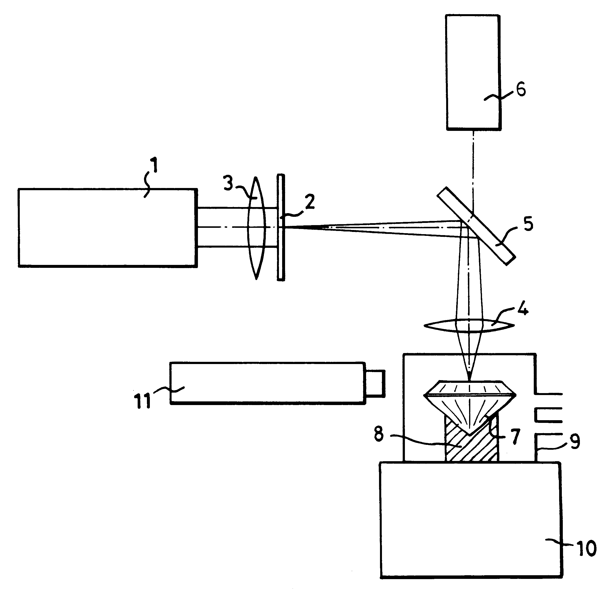
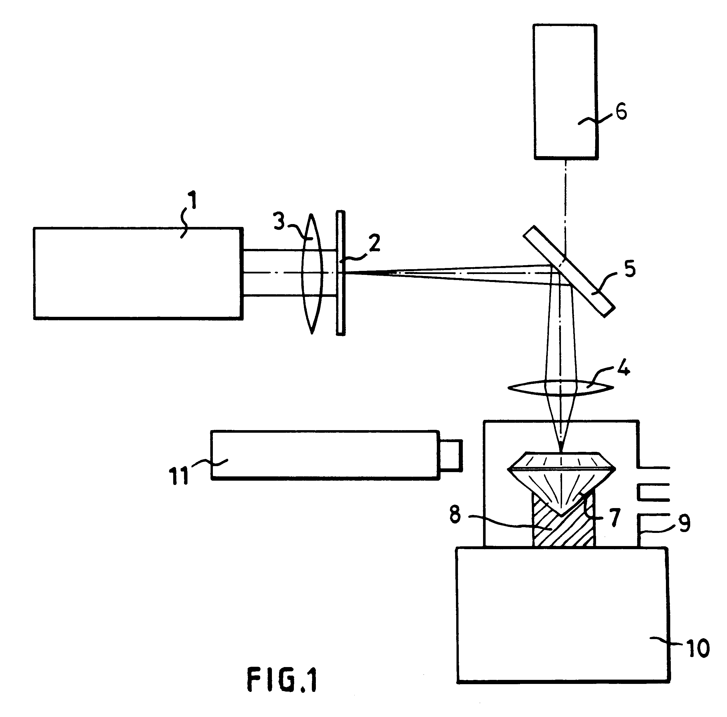
Using Apparatus as in FIG. 1

The laser 1 produced pulses of approximately 30 nanoseconds duration at a rate of 20 Hz. It would be preferable to use a laser with a higher repetition rate, eg 200 Hz, to complete the mark more quickly. The fluence at the diamond 7 was set in the range of 0.2-1.2 J / cm.sup.2 per pulse, a preferred value being about 0.85 J / cm.sup.2 per pulse. Typically, in air (20% oxygen, 80% nitrogen), marks 10-20 nm deep were produced (in 50 seconds) with 1000 pulses. For a given set of process conditions, the depth of the mark is proportional to the number of pulses used in its formation. When the process was carried out in air but with nitrogen purging, ie in an atmosphere of nitrogen with a small percentage of oxygen, etching occurred at a greatly reduced rate; it is believed that no etching would occur in an atmosphere of pure nitrogen. When the process is carried out in a good vacuum (10.sup.-6 mbar), no observable etching takes place.

The marks produced were a sequ...

example 2

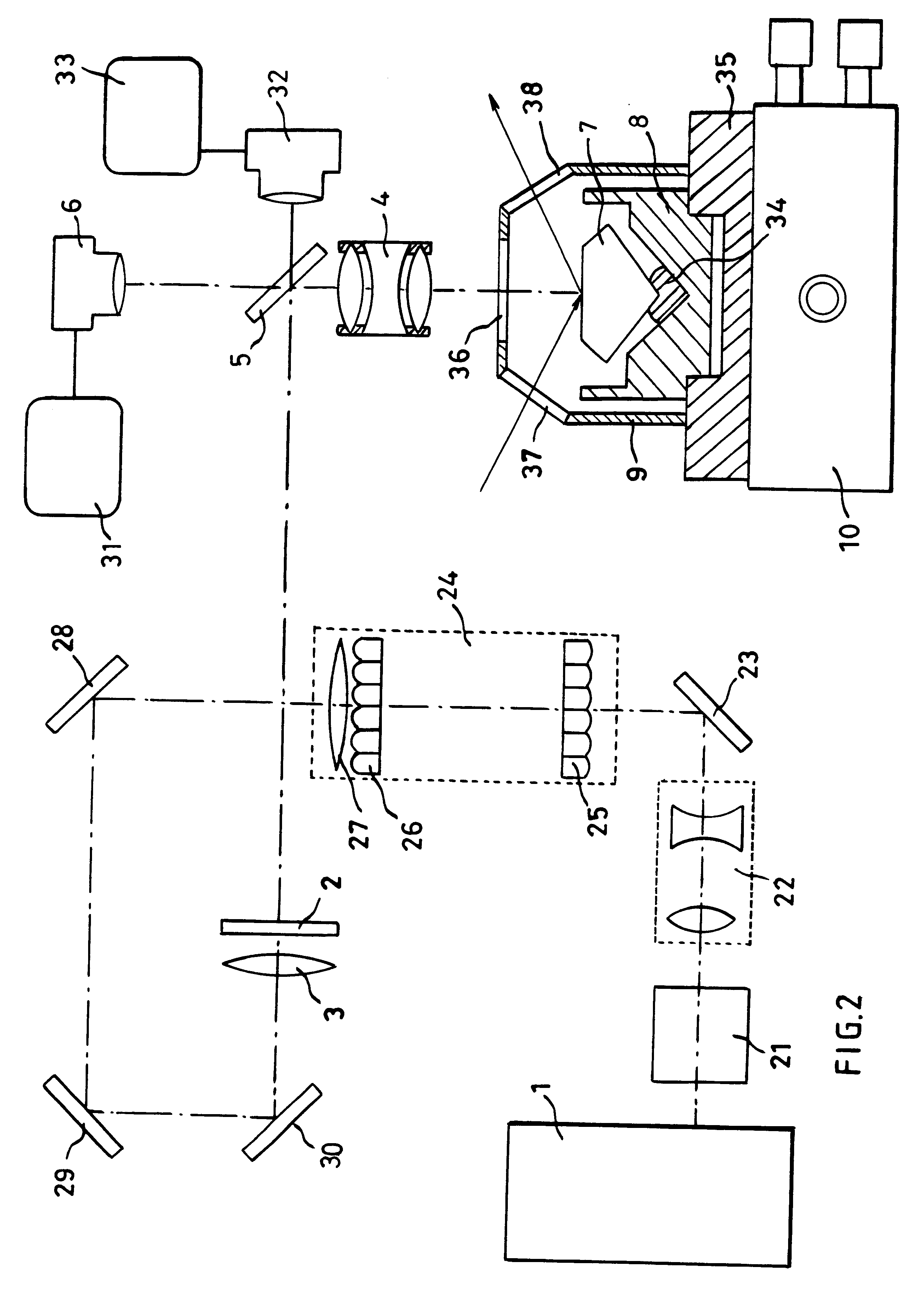
Using the Apparatus of FIG. 2

Diamond surfaces of various crystallographic orientation were irradiated using the apparatus of the second embodiment. The temperature was room temperature. The mask 2 was the 1951 USAF test target. Each irradiated region of the sample was exposed for 4 minutes at a pulse rate of 50 Hz, to deliver 12000 pulses.

It was first observed that the marks produced were of a very high quality with no evidence of the coherence artifacts present in Example 1. Since the irradiation was more uniform, it was possible to work with higher average fluences than in Example 1 without any risk of blackening or ablation near the edges of the marks. Specifically, when working with a reagent atmosphere of oxygen at atmospheric pressure, the maximum fluence that could be safely used was about 1.8 J / cm.sup.2 for orientation surfaces, 2.0 J / cm.sup.2 for surfaces and in excess of 2.2 J / cm.sup.2 for surfaces.

To determine the importance of a reagent atmosphere, a series of irradia...


PUM

PropertyMeasurementUnit
wavelengthaaaaaaaaaa
depthaaaaaaaaaa

Abstract

In order to produce on the table of a diamond gemstone (7), an information mark which is invisible to the naked eye using a x10 loupe, an ultraviolet laser (1) having a wavelength of 193 nm is used in association with a mask (2) to irradiate the surface of the stone (7) at a fluence of less than 2 J / cm2 per pulse and with not fewer than 100 pulses, in the presence of air which reacts with the diamond (7) and causes the mark to be formed without any darkening which is visible when viewing using a microscope.

Description

BACKGROUND TO THE INVENTIONThe present invention relates to a method of producing on a polished facet of a diamond gemstone an information mark which is invisible to the naked eye, comprising using ultraviolet radiation or other radiation to irradiate the surface of the respective portion of the stone. "Invisible to the (naked) eye" means invisible to the (naked) eye of the expert or trained diamond grader. The information mark (which may be called an indicium) may be an identification mark for the diamond but need not identify a particular diamond and in general could give other information such as a quality or trade mark. Normally, the information mark will be a complex mark, not say a simple dot.Such information marks are discussed in U.S. Pat. No. 5,410,125, from column 1, line 40 to column 2, line 2, but the technology of producing information marks on diamonds is also discussed in U.S. Pat. No. 4,392,476, U.S. Pat. No. 4,467,172, U.S. Pat. No. 5,149,938 and U.S. Pat. No. 5,334...

Claims


Application Information

Patent Timeline
Patent Type & Authority Patents(United States)
IPC IPC(8): B23K26/06B44B7/00B41M5/24B23K26/00B28D5/00C30B29/04H01S3/00
CPCB23K26/0656B44B7/00B41M5/24B23K26/066G01N21/87B23K26/361B23K2103/50
Inventor SMITH, JAMES GORDON CHARTERSCOOPER, MARTIN
Owner GERSAN ESTAB
Why Eureka
Try Eureka