Even though the
semiconductor technologies have been developed and the photoelectric conversion apparatuses have been developed which are capable of taking pictures of the images of motion pictures such as a video
cam corder by using a
solid state
image sensing device using a Si
single crystal as represented by the CCD type sensor, the MOS type sensor, these images can not be better than the silver-salt photograph with respect to the number of pixels as well as to the S / N ratio, and thus it has been common to use the silver-salt photographs for taking the static images thereinto.
Although the silver-salt film has advantages such as the silver-salt film has a goood sensitivity, and also has a high quality of resolution, but it has problems such as taking too much time for a development, taking a lot of time and labor for a retention / a management, and not readily to transmitted to a
remote area, and the like, and thus it is desired to have an electronic X-ray image
pickup apparatus which outputs the
digital signal not of similar quality to the silver-salt photograph image as described above.
By adopting the noises with the image data, there is the possibility of resulting damage to the the medical diagnoses and / or the diagnoses of the structures by the non-destructive inspections.
Accordingly, it is very difficult to implement a high quality X-ray diagnostic apparatus for a medical service by a small size photoelectric conversion apparatus using a minature optical
system with a low utilization efficiency of the light, and thus it becomes possible to provide a desired X-ray diagnostic apparatus for a medical service by using a sensor substrate with a large area on which a large number of photoelectric conversion elements, which can utilize the X-ray with a high efficiency and also obtain a high S / N ratio, are arranged two-dimensionally.
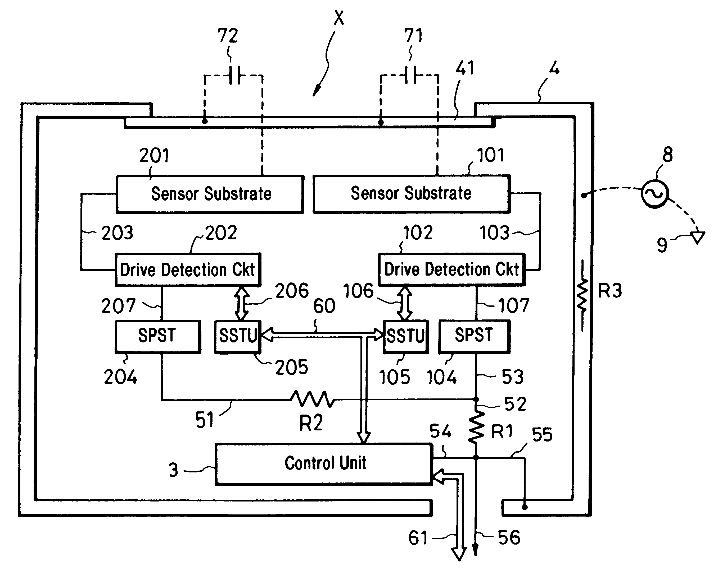
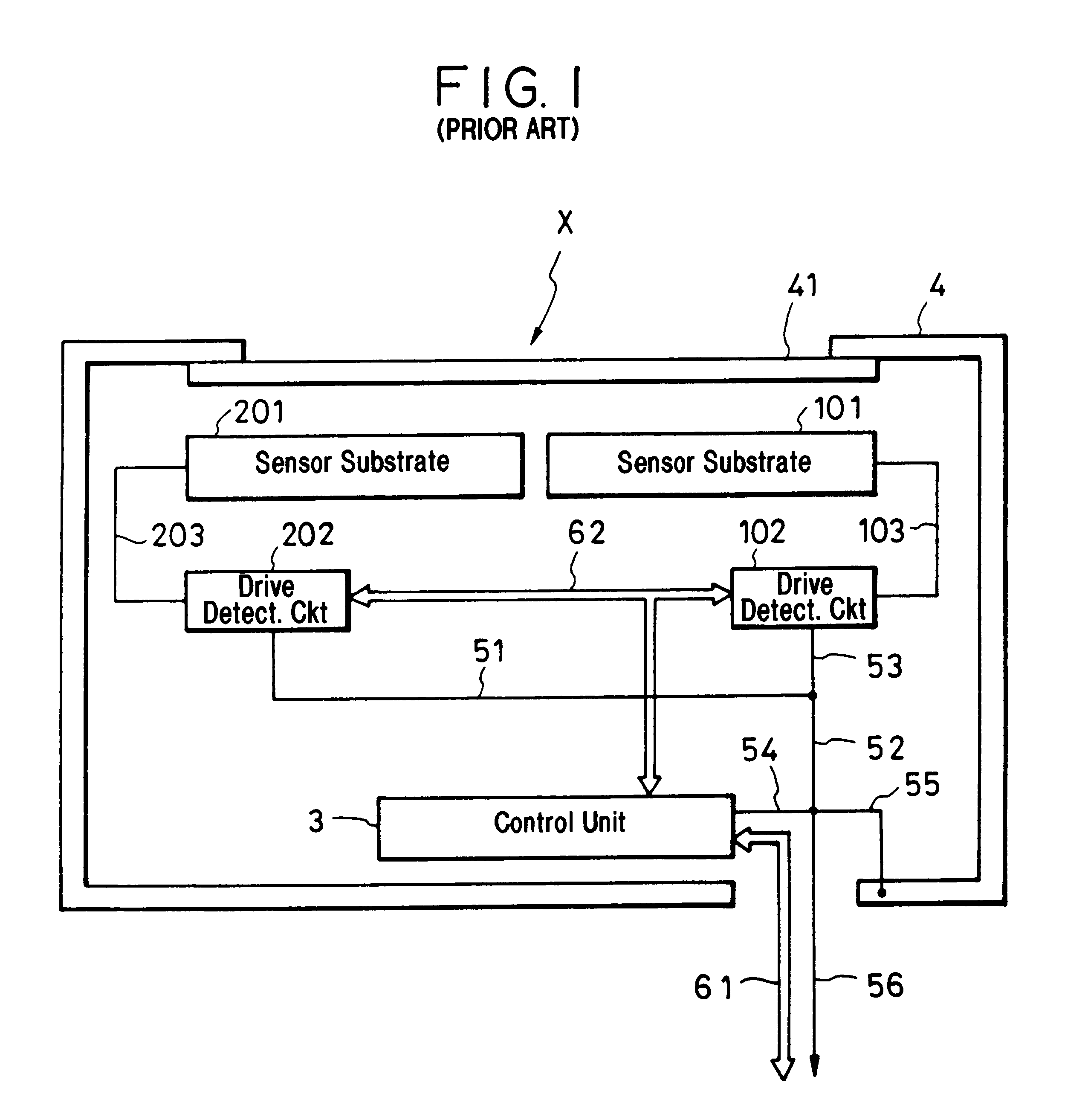
However, with the above described configuration, because of using the sensor substrates with the large area, the X-ray can be utilized with a high efficiency, but there is a possibility of creating problems as described in the following.
A first problem is that since the sensor substrates 101, 201 have the large areas, a
capacitive coupling with the conductive
enclosure is very large, and thus if the conductive
enclosure is slightly shifted with respect to the reference electrical potential within the sensor substrates, it would be influenced substantially.
A second problem is that since the photoelectric conversion elements which readily receive a
noise are formed on the insulating substrates, a stray
capacitance can exist between the conductive
enclosure.
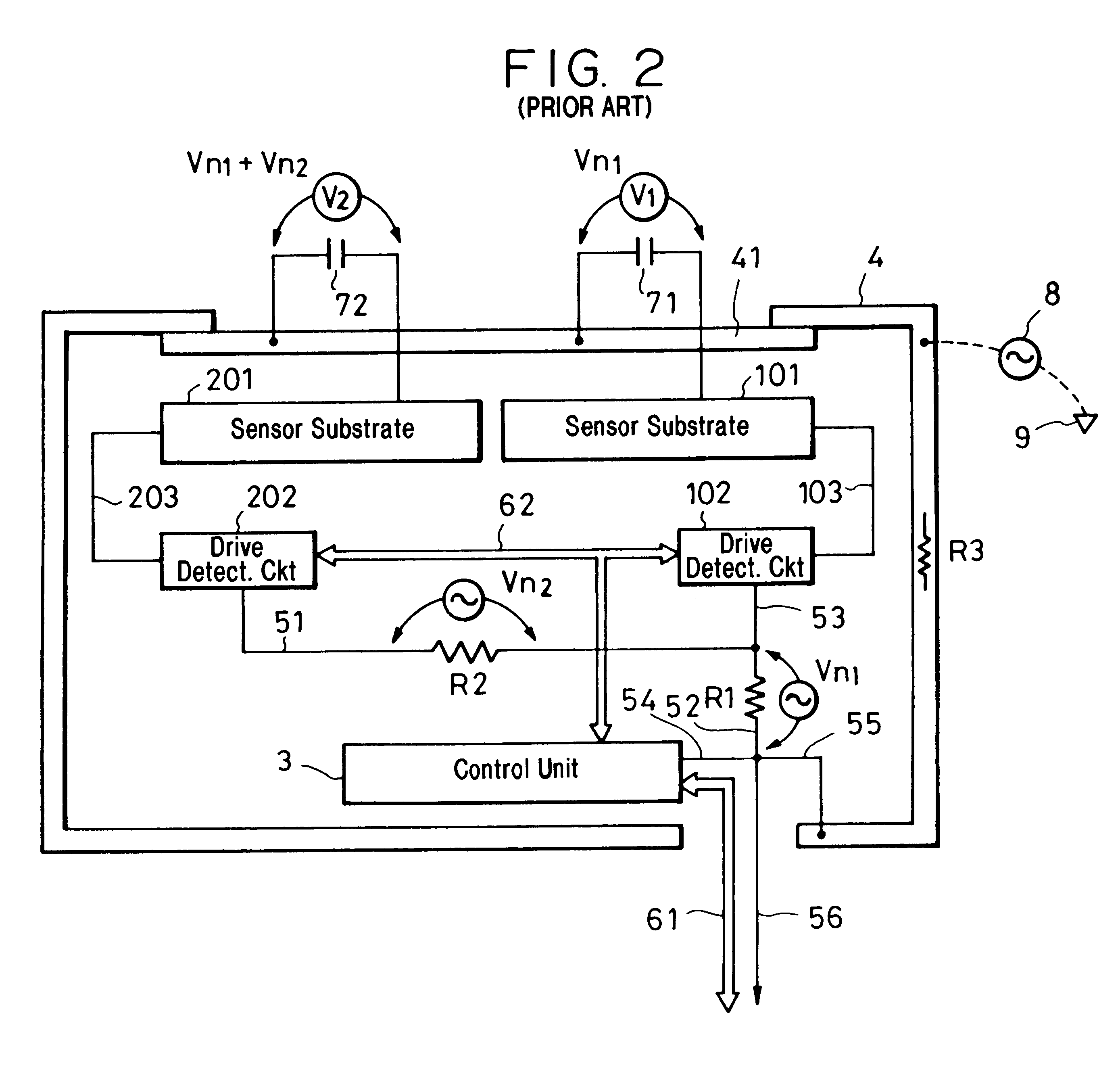
A third problem is that because the shape of the apparatus is large, the wires for connecting the respective parts turn out to be longer, and thus the wires do not work as ideal wires and possess resistance therewith.
This indicates that the electrical potentials would be generated within the wires as current flows through the wires, and causes the noise.
Further, the noise electrical potentials are also added according to the radio
waves and the electrostatic noise generated from the external apparatus.
Further, this
alternate current generates an alternating electrical potential through the
capacitance and the resistance and this also influences the respective parts as noise.
This influence puts the sensor substrates together and constitutes the photoelectric conversion apparatus with much larger area, and thus it has been difficult to obtain a performance with a high S / N.
This noise causes to deterioration of detection ability of an entire apparatus, i.e., a sensitivity that is so-called a S / N ratio.
It is better not to have this resistance, but it is difficult to eliminate the resistance completely.

