
Separation of charged particles by a spatially and temporally varying electric field

Inactive Publication Date: 2001-02-27
CURAGEN CORP
View PDF14 Cites 105 Cited by
  • Summary
  • Abstract
  • Description
  • Claims
  • Application Information

AI Technical Summary

Benefits of technology

It is another object of the method and apparatus of this invention that separation is accomplished with a spatially and temporally varying electric potential. The potential has a plurality of eccentrically-shaped potential wells that trap the charged particles when the potential is relatively strong. Separation occurs as particles diffuse differentially from well to well, based on differences in diffusivity in the separation medium, when the potential is sufficiently weak (or off). It is an advantage that there is no overall electric potential difference along the line of particle separation.
It is an advantage of the method and apparatus of the invention that they can provide the superiorities over the conventional electrophoresis systems listed in Table 1.

Problems solved by technology

Acids Res. 21:1061), acoustophoresis (J. S. Heyman, U.S. Pat. No. 5,192,450), and electrophoresis, are generally inadequate to meet this sequencing goal.
Mass spectrometry requires an expensive mass spectrometer.
Because of this cost, it is unlikely that this method will have widespread applicability.
Sequencing by hybridization is still relatively new and untested.
Liquid chromatography is capable of performing rapid separation of double-stranded DNA fragments, but is limited by poor resolution.
This method is limited by the similarity in the acoustic properties of DNA fragments of similar lengths, preventing effective separation.
This means electrophoretic separation of DNA fragments is difficult in liquids or other media obeying Stokes' Law.
It has proven difficult to make, or "to cast," uniform gels with uniform transport properties.
One major problem is uneven gel shrinkage due to cross-linking during gel polymerization.
The problems in casting a uniform gel also lead to difficulties in producing a uniform and reproducible loading region, into which sample mixtures are placed prior to separation.
In addition to high separation resolution, demands for more rapid electrophoresis have created additional problems for gel manipulation.
However, higher fields, voltages, and velocities lead to increased resistive heating in the gel, and consequently, significant thermal gradients in the gel.
Such thermal gradients cause additional gel non-uniformities that further impair separation resolution.
It has proven even more difficult to cast uniform gels of such thinness and to assure long, parallel, narrow, and closely spaced migration lanes in so thin a sheet.
These separation means create yet a further set of problems.
These capillary arrays are difficult to cast with uniform gels and difficult to load with samples of fragments.
However, single base resolution in such solutions has been limited to DNA chains with fewer than 200 bases and loading the capillaries with samples remains difficult (A. E. Barron et al., 1993, J. Chromatogr. A 652:3; A. E. Barron et al., 1994, Electrophoresis 15:597; and Y. Kim et al., 1994, Anal. Chem. 66:1168).
Small lane size coupled with the desirability of separating many samples in many migration lanes at once creates conflicting physical requirements.
Conventional, flat-plate techniques have only straight, parallel lanes and cannot accommodate these divergent requirements.
This particle size limitation is due to the requirement that the particles to be separated have polarizabilities sufficiently large to be attracted by fields that can be realistically created in a liquid.
Separation of DNA fragments of a few 100's of bases in length, the sizes commonly produced by sequencing reactions or by RFLPs, is out of reach of this or similar polarization-based devices due to practical limits on electric field strength and voltages.
All the foregoing technical problems have hindered creation of a machine for rapid, concurrent analysis of large numbers of biopolymer samples at low cost and with minimal human intervention.

Method used


Image

  • Separation of charged particles by a spatially and temporally varying electric field
  • Separation of charged particles by a spatially and temporally varying electric field
  • Separation of charged particles by a spatially and temporally varying electric field

Examples


Embodiment Construction

Sec. 5.1 describes the structure of an exemplary separation device according to this invention. Sec. 5.2 describes in a summary fashion the operation of a separation method and device. Sec. 5.3 describes in more detail the operation of the separation method and device, and provides a method for the selection of method operating conditions and device design parameters. Sec. 5.4 describes the important case of the separation of DNA. Finally, Sec. 5.5 describes exemplary methods for microfabrication a separation device according to this invention.

5.1. Description of a Separation Device

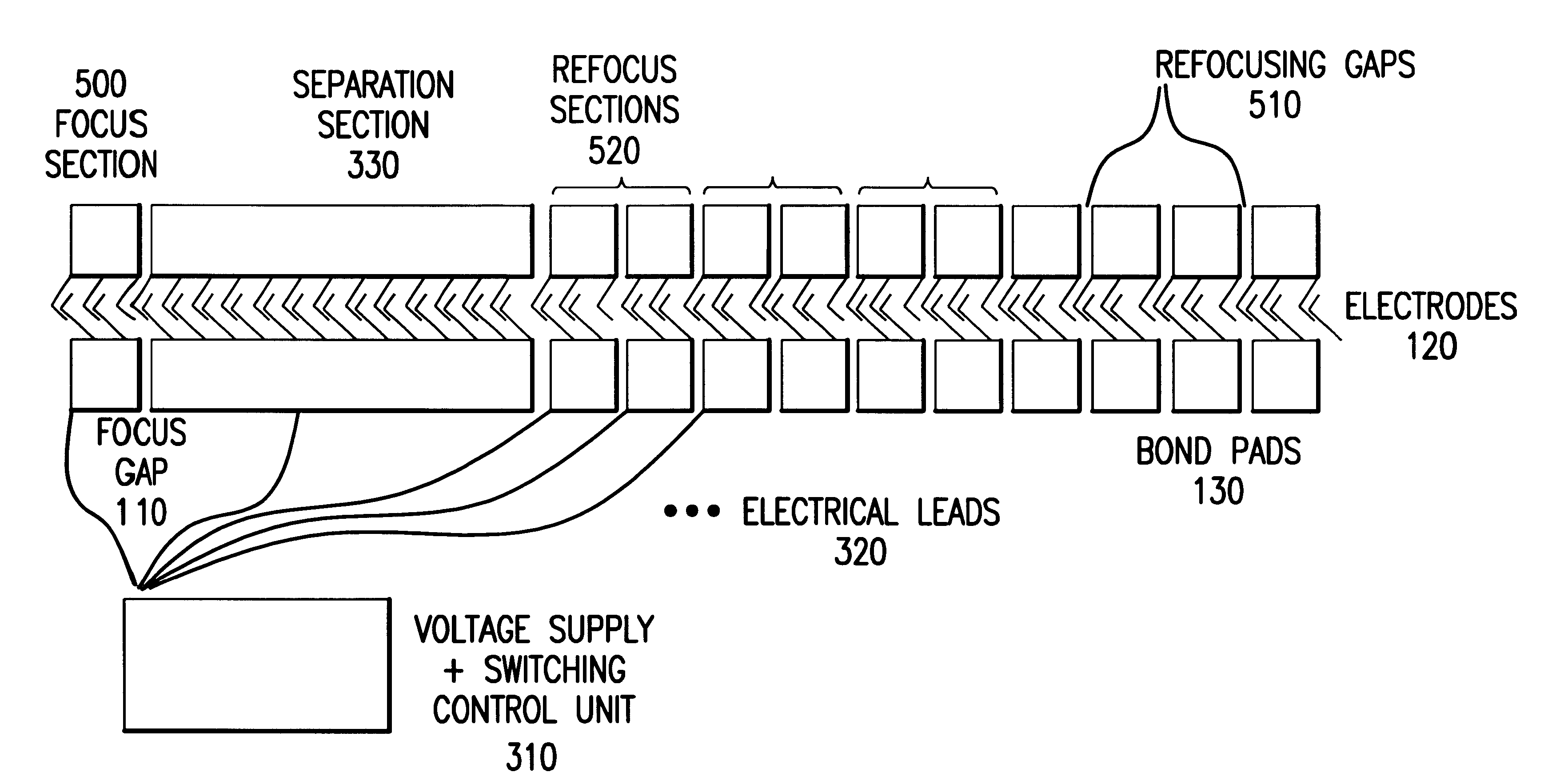
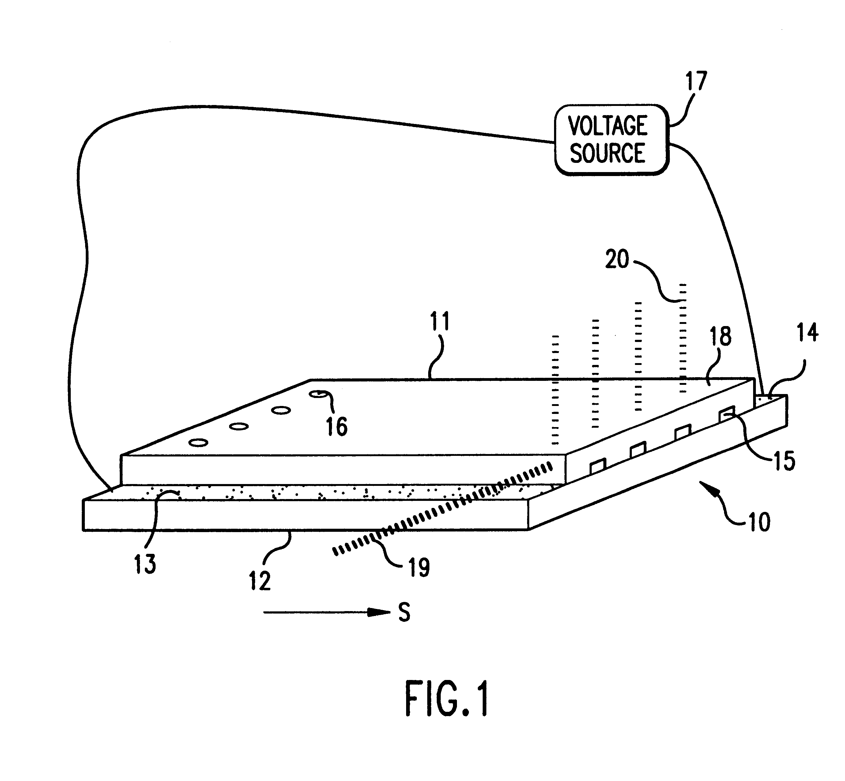
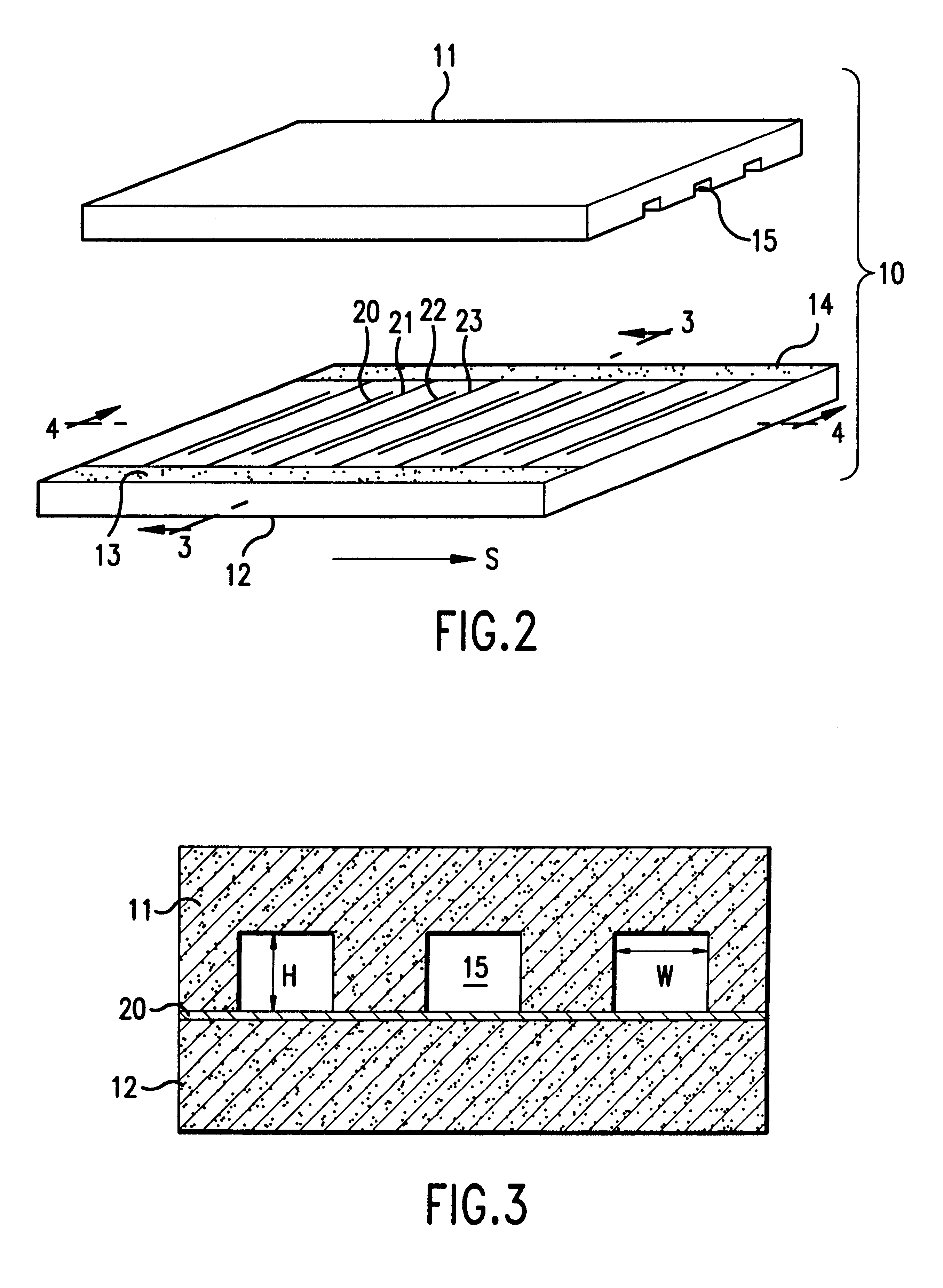
FIG. 1 illustrates a separation device according to this invention. This separation device and its particular embodiments, device types I and II, are the preferred physical structures for the device. However, charged particle separation according to the method of this invention can be practiced in any other physical structure having one or more separation lanes that hold a separation medium and that are s...


PUM

PropertyMeasurementUnit
Lengthaaaaaaaaaa
Lengthaaaaaaaaaa
Lengthaaaaaaaaaa

Abstract

This invention relates to a method and device for separating charged particles according to their diffusivities in a separation medium by means of a spatially and temporally varying electric potential. The method is particularly suited to sizing and separating DNA fragments, to generating DNA fragment length polymorphism patterns, and to sequencing DNA through the separation of DNA sequencing reaction products. The method takes advantage of the transport of charged particles subject to an electric potential that is cycled between an off-state (in which the potential is flat) and one or more on-states, in which the potential is preferably spatially periodic with a plurality of eccentrically shaped stationary potential wells. The potential wells are at constant spatial positions in the on-state. Differences in liquid-phase diffusivities lead to charged particle separation. A preferred embodiment of the device is microfabricated. A separation medium fills physically defined separation lanes in the device. Electrodes deposited substantially transverse to the lanes create the required electric potentials. Advantageously, injection ports allow sample loading, and special gating electrodes focus the sample prior to separation. The effects of thermal gradients are minimized by placing the device in contact with a thermal control module, preferably a plurality of Peltier-effect heat transfer devices. The small size of a microfabricated device permits rapid separation in a plurality of separation lanes.

Description

A portion of the disclosure of this patent document contains material which is subject to copyright protection. The copyright owner has no objection to the facsimile reproduction by any one of the patent disclosure, as it appears in the Patent and Trademark Office patent files and records, but otherwise reserves all copyright rights whatsoever.1. FIELD OF THE INVENTIONThis invention relates to a method and apparatus for the separation of charged particles in a medium according to the differences of the diffusivities of the particles in the medium by use of a spatially and temporally varying electric potential. Particularly, the invention relates to a method and apparatus for separation of charged biopolymers in a liquid medium, and more particularly to a method and apparatus for the separation of single-stranded or double-stranded DNA fragments for DNA sequencing and for general fragment length determination.This invention further relates to a method and apparatus for using electrod...

Claims


Application Information

Patent Timeline
IPC IPC(8): G01N27/447B01D57/02C12M1/00C12N15/09C12Q1/68G01N27/26G01N33/483G01N33/50G01N37/00
CPCB82Y30/00G01N27/44773
Inventor BADER, JOEL S.ROTHBERG, JONATHAN M.DEEM, MICHAEL W.MULHERN, GREGORY T.WENT, GREGORY T.SIMPSON, JOHNHENCK, STEVEN
Owner CURAGEN CORP
Learn More