Two-cycle internal combustion engine with enhanced lubrication

a technology of internal combustion engine and enhanced lubrication, which is applied in the direction of combustion engine, pressure lubrication, machines/engines, etc., can solve the problems of air pollution, piston and cylinder walls scoring or other damage, and affecting the performance of the engine,

Inactive Publication Date: 2001-03-27
BERRY JR WILLIAM H
View PDF7 Cites 27 Cited by
  • Summary
  • Abstract
  • Description
  • Claims
  • Application Information

AI Technical Summary

Benefits of technology

It is another object of the invention to provide a two-cycle internal combustion engine which operates cleanly.
Referring again to FIG. 4, the piston 20 optionally includes a tapered groove 50 formed in the piston head 20A. Groove 50 communicates with the edge of the piston head 20A in the area above the holes 40-43 in the exhaust side of the piston skirt 20B, and extends radially-inwardly towards the center of the piston head 20A. Groove 50 becomes progressively shallower as it progresses radially-inwardly. In the illustrative preferred embodiment set out in this application with a 45 mm diameter piston, the groove 50 is approximately 4 mm wide and 4 mm deep at the edge of the piston head 20A and extends to the center by a distance of approximately 12 mm. Groove 50 functions to cause exhaust gases to flow towards the exhaust port 38 marginally earlier in the exhaust portion of the cycle and thus decreases back pressure in the engine, thus improving engine efficiency. When the piston head 20A reaches the exhaust port 38, exhaust gases have already begun flowing into the exhaust port 38 through the groove 50. In effect, the timing of the exhaust cycle of the engine is advanced very slightly.
Other modifications also improve the operation of the engine 10. As is shown in FIG. 3, an annular groove 55 is formed in the piston pin collar 29, and an annular groove 60 is formed in the crankcase collar 31. These grooves 55 and 60 form reservoirs for gasoline in the crankcase and thus receive some of the additional lubricating gasoline directed into this area by the flow through the holes 41 and 42.
Other considerations for optimum performance include retarding the ignition between 3 and 4 degrees less than typical on such an engine, which will provide less negative crankshaft force. It has also been determined that the thickness of the piston head 20A need be no more than approximately 4 mm thick. This reduces the weight of the piston 20 and produces further efficiencies, including less mass to move to create a given amount of energy, and greater heat transfer.

Problems solved by technology

On the other hand, the exhaust side of the piston is exposed to extremely high friction which can easily cause scoring or other damage to the piston and cylinder walls on the exhaust side.
Mixture of lubricating oil with gasoline in such engines creates a number of problems.
The remaining oil is exhausted as a blue / gray exhaust stream which has an foul odor, creates air pollution, and coats environmental surfaces with which it comes into contact.
Some amount of the oil remains in the engine and eventually fouls the spark plug, cylinder walls and piston components.
The oil component of the gasoline / oil mixture is also quite expensive in relation to the ratio used, and adds an inordinate amount to the overall fuel costs.
These disadvantages have caused more expensive, heavier and lower efficiency four-cycle engines to be used for many applications where a two-cycle engine could otherwise be used.
Damage in such two-cycle engines is principally to the exhaust side of the engine, and is caused by lack of lubrication.

Method used


Image

  • Two-cycle internal combustion engine with enhanced lubrication
  • Two-cycle internal combustion engine with enhanced lubrication
  • Two-cycle internal combustion engine with enhanced lubrication

Examples


Embodiment Construction

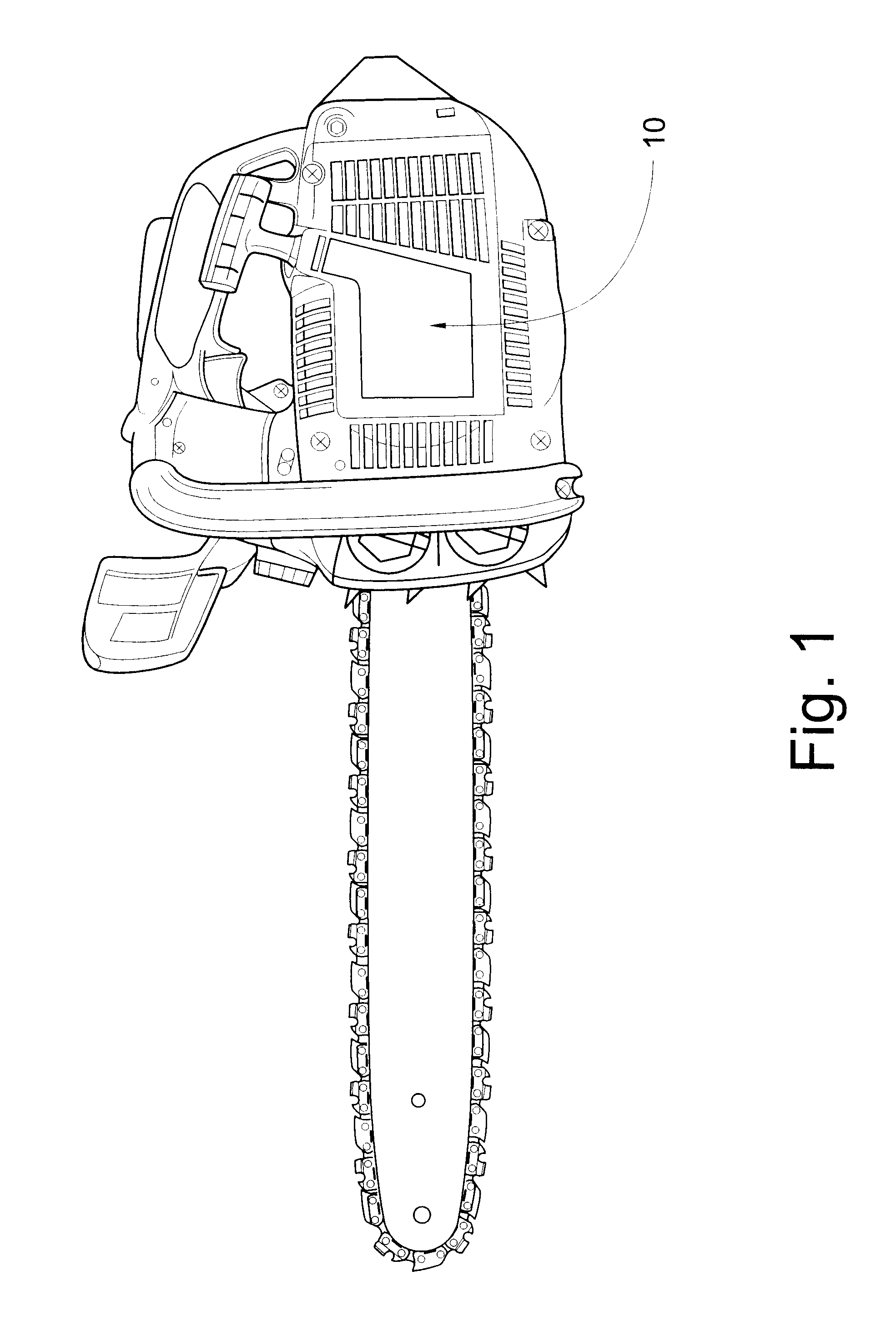
Referring now specifically to the drawings, a two-cycle gasoline internal combustion engine according to the present invention is illustrated in FIG. 1 and indicated generally at reference numeral 10. The engine 10 is shown as used in a typical application to power a chain saw. The principles of the invention have application in many different uses and can be used on two-cycle engines of many different types and sizes.

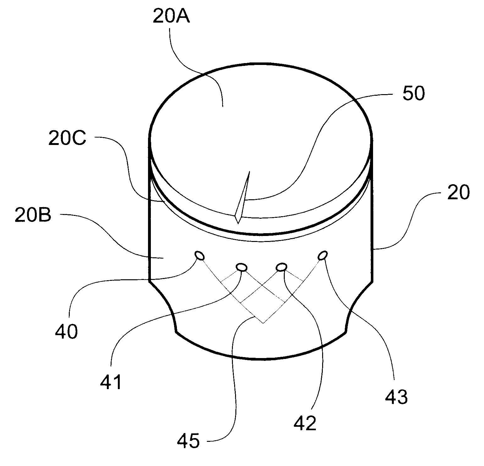
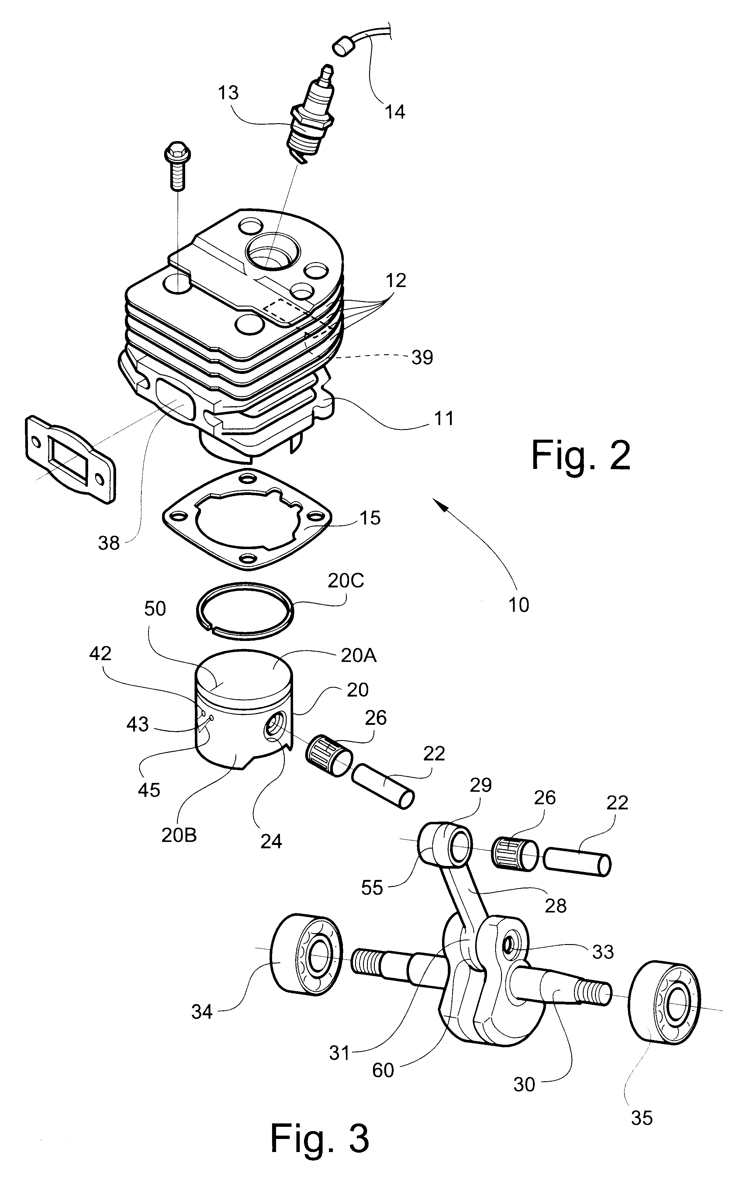
Relevant parts of the engine 10 are shown in greater detail in FIGS. 2 and 3, and include an engine cylinder block 11, cooling fins 12, a spark plug 13 with an electrical lead 14, and a cylinder gasket 15. A piston 20 is mounted in a conventional manner in the cylinder block 11 for reciprocating movement. Piston 20 defines an annular piston head 20A and an integrally-formed cylindrical skirt 20B. Skirt 20B receives a piston ring 20C which engages the inner cylindrical walls of the cylinder block 11. Piston 20 also includes a piston pin 22 which is mounted in a piston p...


PUM


Abstract

A gasoline internal combustion engine, including an engine block having a cylinder, fuel intake port and exhaust port therein. A piston is mounted in the cylinder for two-cycle, reciprocating movement therein, and includes an annular piston head and a cylindrical piston skirt, a connecting rod rotatably-mounted by a top end thereof to a piston roller bearing carried on a piston pin of the piston, and by a bottom end of the connecting rod to a crankshaft for outputting power from the reciprocating piston, the crankshaft mounted on a pair of spaced-apart crankshaft roller bearing assemblies, and an array of holes extending through the piston skirt for drawing gasoline from an opposing fuel intake side of the piston to the exhaust side of the piston on the downstroke of the piston to lubricate the exhaust side of the piston and cylinder without the mixture of engine oil with the gasoline.

Description

TECHNICAL FIELD AND BACKGROUND OF THE INVENTIONThis invention relates to two-cycle internal combustion engines. Such engines are used in a very wide variety of applications, for example, lawn mowers, string trimmers, snow and leafblowers, personal watercraft such as "jet-skis", motorcycles, boats and chain saws. Such engines are typically lubricated by means of oil mixed with raw gasoline in some fixed ratio, for example 50 parts of gasoline to 1 part oil instead of an oil-filled crankcase, as in four-cycle engines. The term "two-cycle" is actually a shortened version of "two-stroke cycle", and refers to the fact that each cycle of the engine is completed in two strokes of the piston--one up and one down. The engine must be designed so that the combustion chamber can be supplied with a fresh charge of fuel when the piston is in the extreme outward position.In most two-cycle engines, valves are replaced by ports in the cylinder, through which fuel is drawn into the cylinder and exhau...

Claims


Application Information

Patent Timeline
Patent Type & Authority Patents(United States)
IPC IPC(8): F01M1/00F01M1/08F01M9/00F01M9/04F02B75/02F02B63/02F02B63/00
CPCF01M1/08F01M9/04F01M2001/083F02B63/02F02B2075/025
Inventor BERRY, JR., WILLIAM H.
Owner BERRY JR WILLIAM H
Why Eureka
Try Eureka