Process for manufacturing an electromagnetic interference shielding metallic foil cladded plastic product

a technology of electromagnetic interference and metallic foil, which is applied in the direction of ceramic layered products, chemistry apparatus and processes, manufacturing tools, etc., can solve the problems of difficult to manufacture metallic shields with intricate shapes, the risk of damage to other equipment or components, and the risk of dense electromagnetic waves produced by electronic equipmen

Inactive Publication Date: 2001-03-27
NAT SCI COUNCIL
View PDF14 Cites 64 Cited by
  • Summary
  • Abstract
  • Description
  • Claims
  • Application Information

AI Technical Summary

Problems solved by technology

However, the high-density electromagnetic waves produced from electronic equipment have the risk to damage or adversely affect the performance of other equipment or components.
Also, exposure to electromagnetic waves is harmful to the human body.
However, metallic shields with intricate shapes were difficult to be fabricated by the conventional metalworking methods.
Moreover, metallic shields were cumbersome, heavy and costly.
Unfortunately, the results obtained with metallic coatings were not always satisfactory.
In addition to being relatively non-economical, once such metallic coatings were scratched through, they would lose part of their shielding efficiency.
Frequently, it was difficult to obtain a dependable, 100% effective coating which was also resistant to peeling.
However, during the compounding with the resin matrix, the conductive powders may easily cluster, and thus are not capable of dispersing in the resin matrix.
Consequently, the electromagnetic shielding efficiency of the molded products can not be effectively improved.
Consequently, the mechanical properties, color and other physical and chemical properties of the molded products are adversely affected.
However, the cluster phenomenon is still difficult to prevent.
However, such a strong conductive filler is very expensive, and is thus not suitable for ordinary low cost electronic equipment.
More seriously, when the resultant plastic pellets containing such conductive filler with high strength are subjected to injection molding, the mold, screws and compressing cylinder walls of the injection machine will suffer extensive wear.
However, again, when the resultant plastic pellets containing a conductive filler with high strength are subjected to injection molding, the mold, screws and compressing cylinder walls of the injection machine will suffer extensive wear.
However, in the injection molding step, such aluminum foil with lower strength has a higher possibility of breaking.
When injection molding is employed, in order to prevent lag, segregation, and orientional phenomena from occurring to the metallic filler in the mold, the design of the mold is very critical and complicated, thus increasing costs.
Moreover, if a very thin product is desired, such as the outer shell of a notebook computer, the design of the mold is difficult, or even impossible to achieve.
In addition, floating phenomenon in the final conductive plastic article can not be prevented.
Therefore, surface plastic coating on the final conductive plastic article is required, thereby increasing cost.
Therefore, the resulting electromagnetic shielding effectiveness of such plastic article is limited and far less than that of a conventional metal outer shell.
However, a plastic article containing discontinuous (non-solid) conductive filler obtained from the above three methods has a shielding effectiveness of only about 50 dB, which can only meet the requirements for simple electronic equipment (40 dB), such as personal computers.
Obviously, the plastic articles obtained from the above three methods will not meet the future needs.
Furthermore, the conductive component-filled plastic articles obtained from the above three methods obviously can not be used for shielding the electronic equipment which needs high shielding effectiveness, such as work stations, remote control systems, cellular phones, and notebook computers.

Method used


Image

  • Process for manufacturing an electromagnetic interference shielding metallic foil cladded plastic product
  • Process for manufacturing an electromagnetic interference shielding metallic foil cladded plastic product
  • Process for manufacturing an electromagnetic interference shielding metallic foil cladded plastic product

Examples


Embodiment Construction

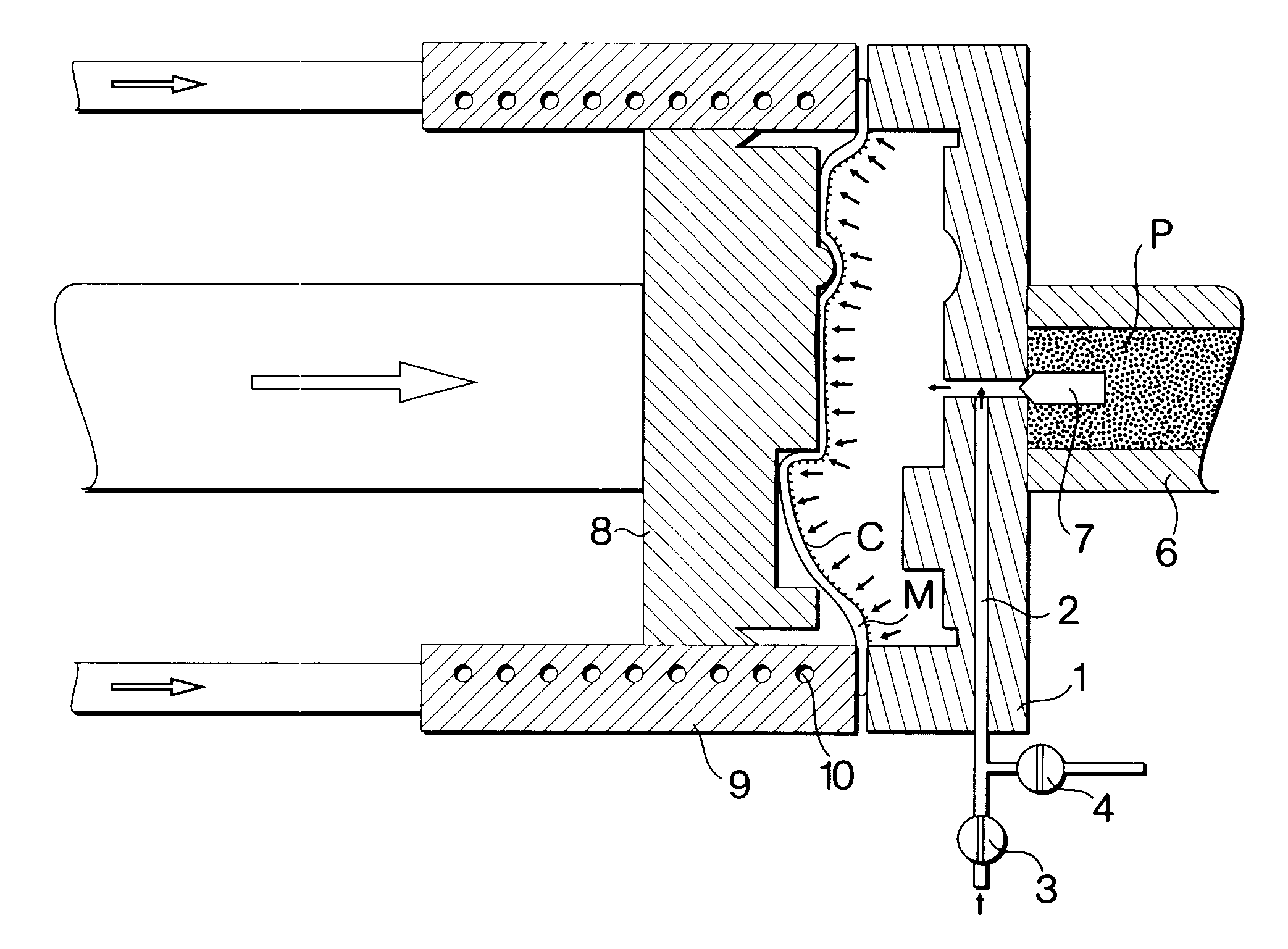
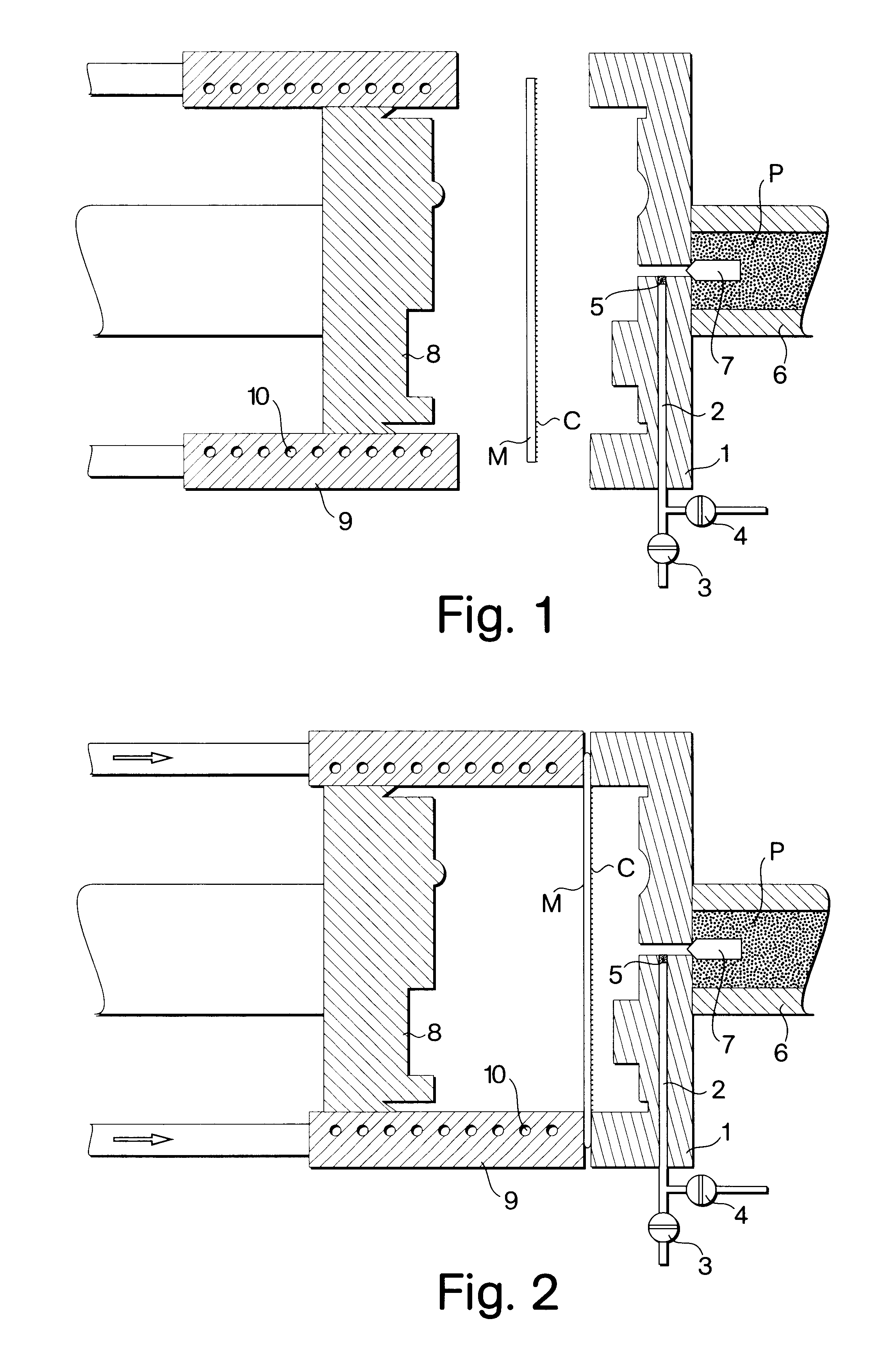
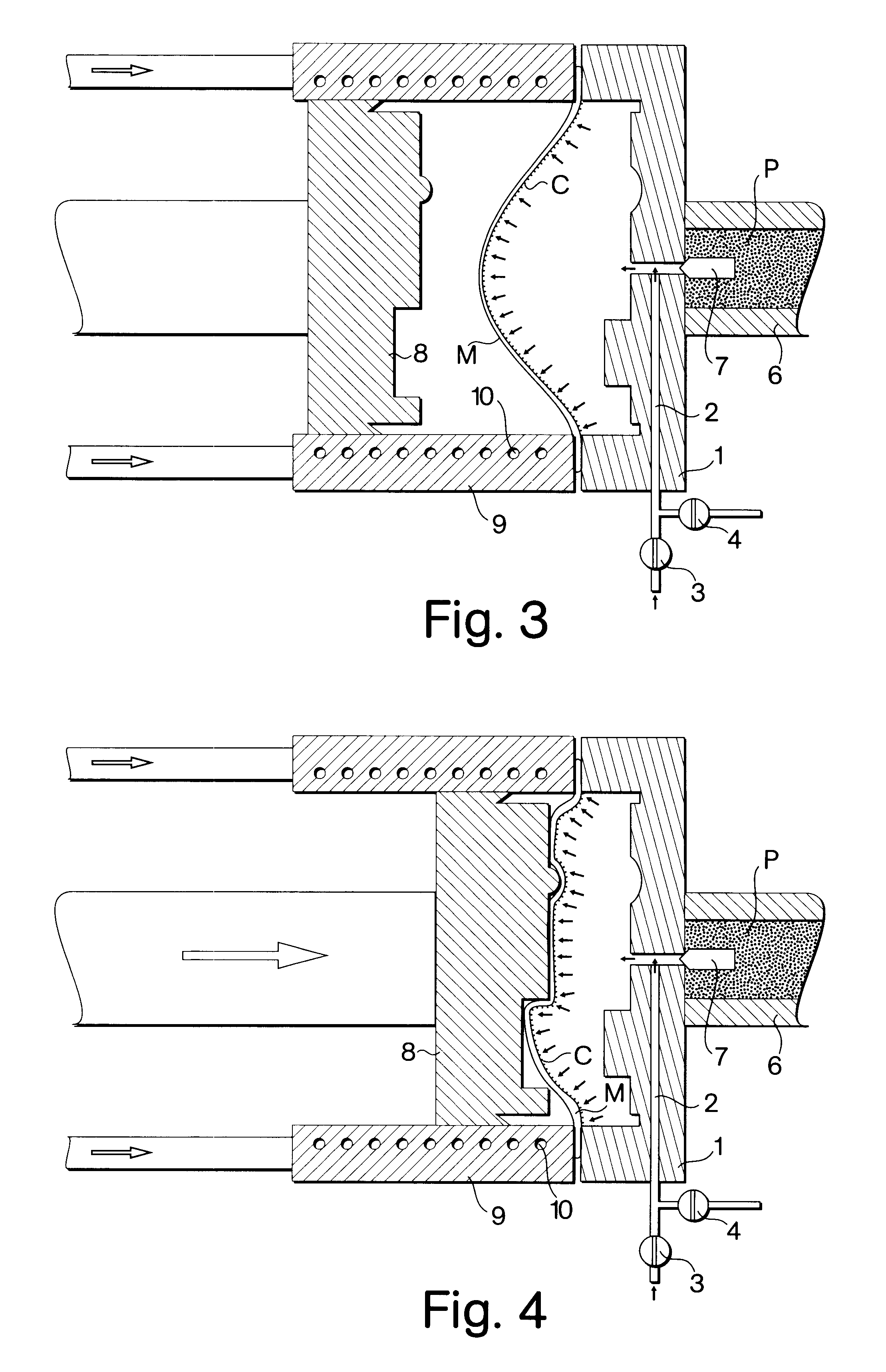
The process was conducted according to the above descriptions. A coupling agent (Silane A-187 manufactured by UNION CARBIDE Chemicals and Plastics Company) was mixed with ethanol to a 1 wt % solution. A Zn-22Al superplastic alloy plate of 0.3 mm was sprayed with the coupling agent solution on one side. The pre-coated Zn-22Al plate was placed in a mold to be processed according to the above-mentioned process of the present invention. The mold was heated and maintained at 200.degree. C., and an argon atmosphere having a pressure of 0.1 kg / mm.sup.2 was introduced to the mold to superplastically blow the Zn-22Al plate into a foil about 0.2 mm thick.

Then, the argon pressure was shut off and the mold was evacuated to a reduced pressure of 10.sup.-3 Torr. Subsequently, softened ABS+20 wt. %PC was injected to the mold from the injection machine, and adhered onto one surface of the Zn-22Al foil. The ABS+20 wt. %PC so adhered has a thickness of about 1.8 mm.

The total thickness of the final el...


PUM

PropertyMeasurementUnit
temperatureaaaaaaaaaa
shielding effectivenessaaaaaaaaaa

Abstract

The present invention provides a process and apparatus for manufacturing an electromagnetic interference shielding metallic foil cladded plastic product. The process comprises (a) coating one side of a superplastic alloy plate with a coupling agent or a hot melt adhesive; (b) placing the coupling agent- or hot melt adhesive-coated superplastic alloy plate in a mold, and superplastically forming the superplastic alloy plate to a superplastic alloy foil with a predetermined shape, such that another side of the superplastic alloy foil is attached to the mold and the coupling agent- or hot melt adhesive-coated side of the superplastic alloy foil is spaced apart from the mold to form a mold cavity, wherein an injection machine is attached to the mold cavity, and wherein the injection machine is capable of injecting softened plastic into the mold cavity; (c) introducing softened plastic from the injection machine to the mold cavity, such that plastic adheres on the coupling agent- or hot melt adhesive-coated side of the superplastic alloy foil, and an electromagnetic interference shielding metallic foil cladded plastic product is formed; and (d) removing the plastic product from the mold. The final metallic plastic product can not only have as intricate a shape as an ordinary plastic product, but also has a shielding effectiveness as high as an ordinary metallic shield.

Description

1. Field of the InventionThe present invention relates to a process and apparatus for manufacturing an electromagnetic interference shielding metallic foil cladded plastic product, and more particularly to a process and apparatus for manufacturing an electromagnetic interference shielding metallic foil cladded plastic product by using two techniques, the superplastic forming of a superplastic alloy and the injecting of softened plastic.2. Description of the Prior ArtIn recent years, progress in technology has led to an extensive increase in the amount of sophisticated electronic equipment. However, the high-density electromagnetic waves produced from electronic equipment have the risk to damage or adversely affect the performance of other equipment or components. Also, exposure to electromagnetic waves is harmful to the human body. Therefore, an electrically conductive outer shell is needed to shield electromagnetic interference (EMI) produced from electronic equipment.Heretofore, v...

Claims


Application Information

Patent Timeline
Patent Type & Authority Patents(United States)
IPC IPC(8): B21D26/02B21D26/00B29C45/14B21D26/055
CPCB21D26/055B29C45/1418B29C45/14311B29C45/14778Y10T29/49986B29K2705/00B29K2715/006B29K2995/0011Y10T29/49805B29C2045/14213
Inventor CHUANG, TUNG-HAN
Owner NAT SCI COUNCIL
Why Eureka
Try Eureka