
Solid electrolytic capacitor and manufacturing method thereof

a technology of solid electrolytic capacitors and manufacturing methods, which is applied in the manufacture of electric ectrolytic capacitors, variable capacitors, fixed capacitor details, etc., can solve the problems that niobium solid electrolytic capacitors cannot achieve a practical level, and the use of aluminum and tantalum is limited

Inactive Publication Date: 2001-04-10
TOKIN CORP
View PDF9 Cites 65 Cited by
  • Summary
  • Abstract
  • Description
  • Claims
  • Application Information

AI Technical Summary

Benefits of technology

According to the present invention, it is possible to remarkably restrain the fluctuation of a capacitance in a reflow step during the mounting of parts.
The present inventors can presume this reason as follows. That is to say, in a heating step such as the reflow step, oxygen diffusion occurs from the niobium oxide layer to the base side of the niobium anode, so that the capacitance increases. In this heating step, however, nitrogen contained in the dielectric layer does not diffuse so much as oxygen. In consequence, a relative ratio of the nitride in the dielectric layer increases. Here, a dielectric constant of niobium nitride is lower as compared with that of niobium oxide, and therefore, the increase of the relative ratio of the nitride leads to the effect of lowering the capacitance. As described above, the present inventors can suppose that the increase of the capacitance by the diffusion of oxygen is offset by the increase of the relative ratio of the nitride having a low dielectric constant.

Problems solved by technology

Among them, the practical metals are limited to aluminum and tantalum at present.
For this reason, the niobium solid electrolytic capacitor cannot attain a practical level.

Method used

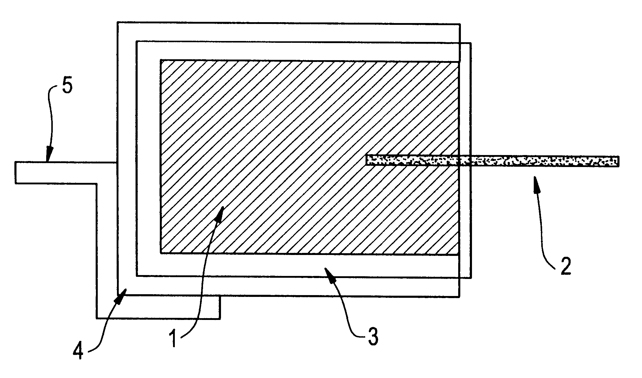
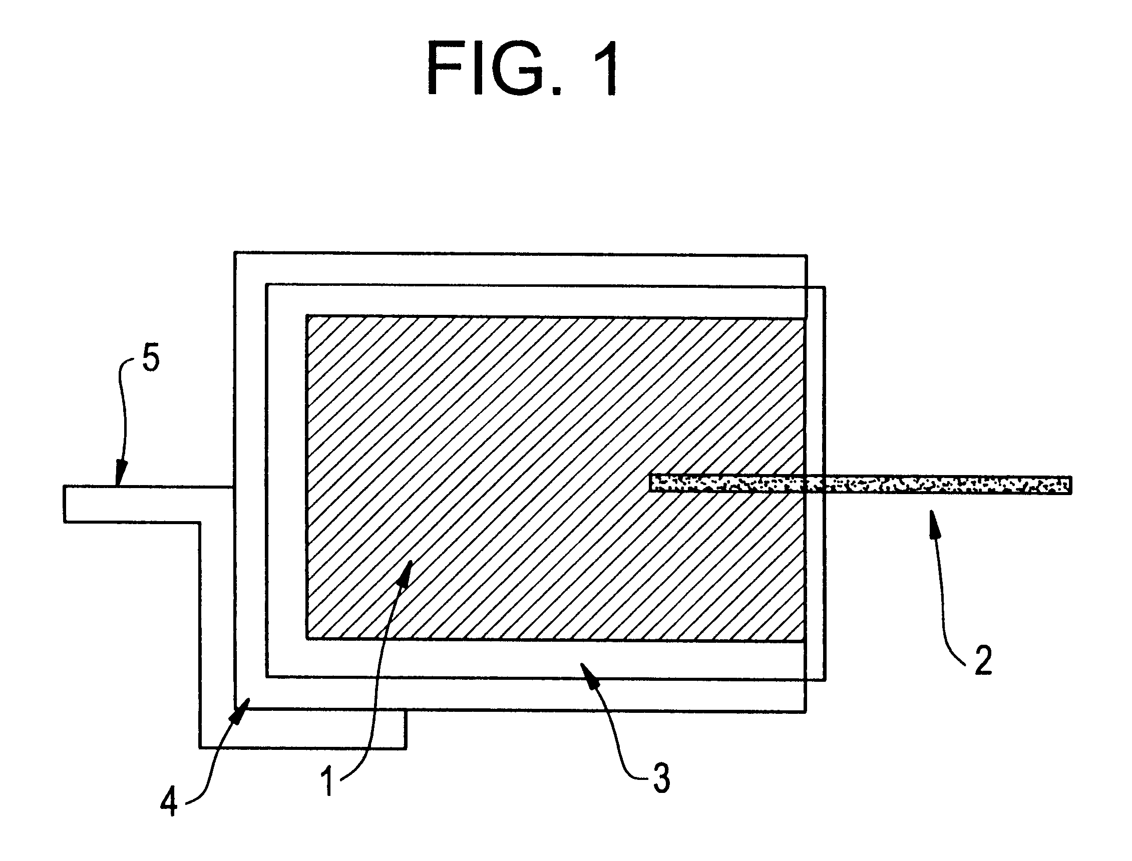
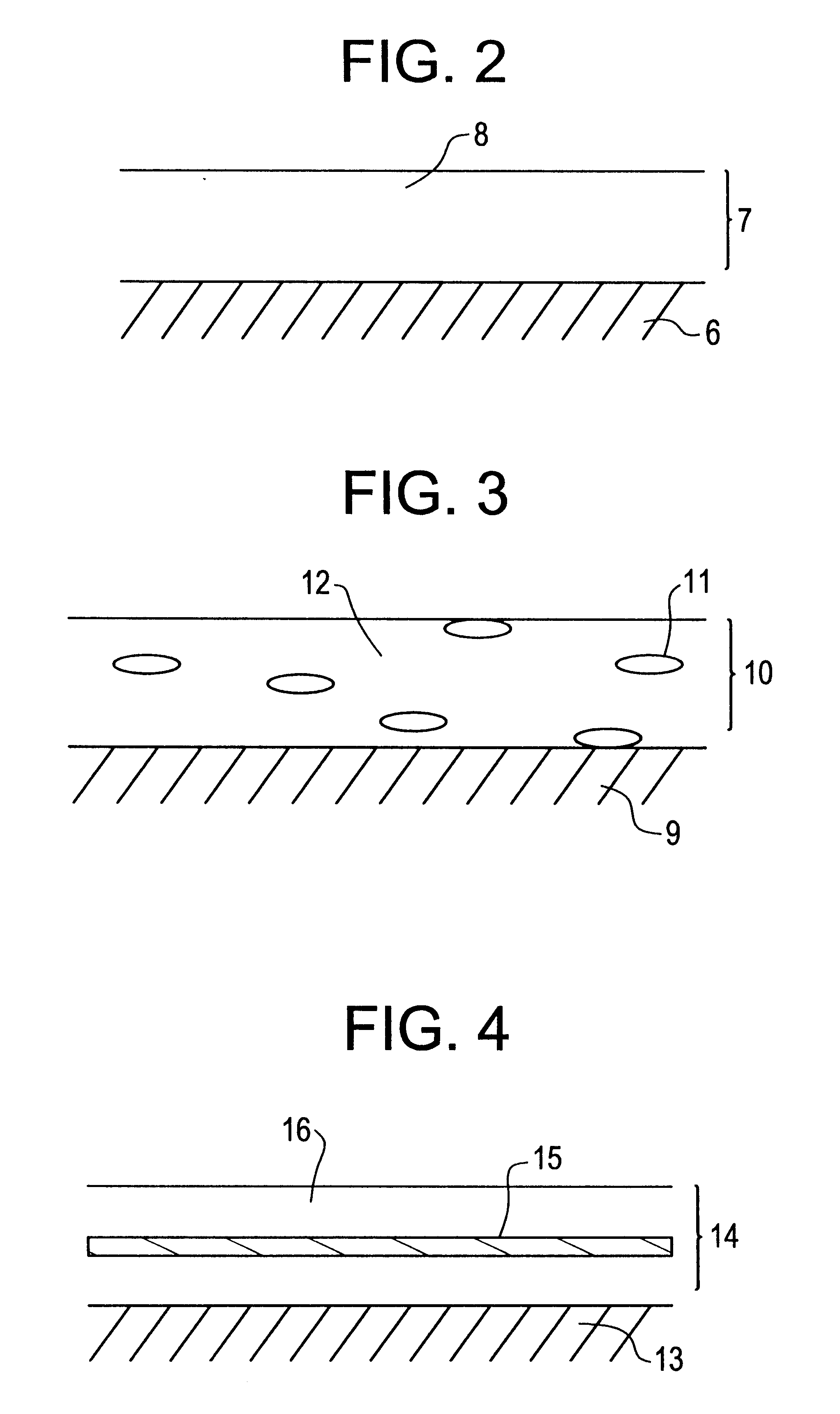

Image

  • Solid electrolytic capacitor and manufacturing method thereof
  • Solid electrolytic capacitor and manufacturing method thereof
  • Solid electrolytic capacitor and manufacturing method thereof

Examples


examples 2 to 5

The same procedure as in Example 1 was conducted except that a nitriding treatment was carried out at each temperature shown in Table 1 and a nitrogen content to an anode obtained by sintering was altered as shown in Table 1, thereby manufacturing solid electrolytic capacitors. The results of the change rate of a capacitance are shown in FIG. 7, and the results of evaluation of a leakage current are shown in FIG. 8.

It is apparent from the results of Examples 1 to 5 that the change rate of the capacitance is reduced by the nitriding treatment and so an effect is observed. In this case, however, the value of the leakage current of the capacitor also increases. Therefore, in view of the valance of both the factors, the nitrogen content is preferably in the range of 900 to 3000 ppm, and it is most preferably in the range of 900 to 2300 ppm in which the change rate of capacitance is in the range of .+-.20%.


PUM

PropertyMeasurementUnit
thicknessaaaaaaaaaa
temperatureaaaaaaaaaa
average particle diameteraaaaaaaaaa

Abstract

A solid electrolytic capacitor is here disclosed in which a dielectric layer formed on the surface of an anode obtained by molding and then sintering a niobium metal powder which includes a niobium oxide layer and a niobium nitride region, and a method for manufacturing the solid electrolytic capacitor is also disclosed.

Description

(i) Field of the InventionThe present invention relates to a solid electrolytic capacitor in which niobium is used as an anode (hereinafter referred to as "the niobium solid electrolytic capacitor"), and more specifically, it relates to a solid electrolytic capacitor in which the change of a capacitance before and after a reflow step can be restrained, and a manufacturing method of the solid electrolytic capacitor.(ii) Description of the Prior ArtA solid electrolytic capacitor generally comprises an oxide layer as a dielectric layer on the surface of a valve action metal sinter, a cathode layer formed thereon, and a cathode outgoing lead extending from the cathode layer.Here, the above valve action metal sinter can be obtained by compressing / molding a valve action metal powder, and then heating the thus molded article at a high temperature in vacuum. On the other hand, the oxide layer can be formed by anodization.The valve action metal means a metal having a valve action, and exampl...

Claims


Application Information

Patent Timeline
Patent Type & Authority Patents(United States)
IPC IPC(8): H01G9/04H01G9/048H01G9/052H01G4/06H01G9/00H01G9/042
CPCH01G9/0032H01G9/042Y10T29/417
Inventor YOSHIDA, KATSUHIROKUGE, NORIKO
Owner TOKIN CORP
Learn More