Wood heater

a wood heater and solid fuel technology, applied in the direction of gaseous heating fuel, stoves or ranges, ways, etc., can solve the problems of poor or unpredictable performance, difficult control of operator performance, and circumvent the intent of mandating

Inactive Publication Date: 2001-04-17
CHAMPION MARK
View PDF13 Cites 11 Cited by
  • Summary
  • Abstract
  • Description
  • Claims
  • Application Information

AI Technical Summary

Problems solved by technology

Poor or unpredictable performance, in effect, circumvents the intent of mandating EPA certified wood heaters since emissions of pollutants are not controlled as desired.
While the factors of fuel quality and mechanical degradation can be remedied, operator performance is very difficult to control.
Further and more specifically, current technology wood stoves have operator controls which if used improperly can cause poor performance.
If the bypass damper does not get actuated or the catalyst itself is not sufficiently heated and the stove is banked soon after fuel loading, the catalyst might not get lit and no emissions reductions are achieved.
Similarly, there is opportunity for non-catalytic stoves to be banked too soon, even when using proper fuel, since preheating of the secondary air system is necessary to combust volatile organic materials evolved from the wood.
These scenarios are supported in the field data and are considered undesirable.
Since masonry heaters and fireplaces are not affected facilities under federal law, no means of certifying their performance exists and the devices cannot be installed, or in some cases even used, in these localities.
EPA certified wood stoves using current technology emissions control systems attempt to fill the need of fireplace customers however, the expense of added operator controls, pollution reduction equipment and, in general, heavier airtight welded construction make the cost of these devices higher than is desirable.
Also, the complexity of user controls is higher than it need be for primarily decorative appliances, possibly resulting in operator error and less than desirable performance.
Inefficiencies of fireplaces result from high fuel burning rates and high air-to-fuel ratios as compared to wood stoves which are primarily intended for heating.
Combustion efficiency can be relatively good due to the abundance of air and the presence of flaming; however, too much air can have a quenching effect which inhibits efficient combustion.
Even if the combustion efficiency is relatively high (as indicated by low pollutants per unit mass of fuel), the uncontrolled high fuel burning rate can result in high emission rates (mass of pollutant per unit time), which is the measure of emissions of primary concern to air pollution regulators.
Indeed, "fireplaces" and "woodstoves" have been in existence for hundreds of years but operationally, efficiency and pollution concerns still exist which are not adequately addressed with the current state of the art.
Un-regulated wood burning systems have low heating efficiency due to high flow rates of combustion or cooling air while regulated systems exhibit low combustion efficiency as a result of operating in a fuel rich range which, in turn, results in incomplete combustion of the organic components of the fuel and higher emissions.
While combustion efficiency is quite good relative to fuel-rich devices, low overall efficiency can result if the high sensible heat loss resulting from high air flow and relatively high fuel burning rates is not recovered.
However, the known prior art devices are not operable at an average fuel consumption rate below 5 kg / hr when tested using accepted industry standards and in fact, in many instances, are intended to operate at much higher burn rates.
This results in less than desirable efficiency for the reasons stated above.
However, as in all known prior art relating to fuel rich wood burning devices, the Lynch system includes an adjustable air introduction system for "providing exactly the amount of air desired for proper combustion", but the proper amount of air is not specified.
If the clean-up technology is ineffective (do to inefficiency, degradation or improper use) no emissions reduction is achieved.
Furthermore, the minimum combustion air setting limits the amount of combustion air entering the combustion chamber such that too much air is not introduced resulting in inefficiency due to sensible heat loss, chemical loss (pollution), quenching of the flames, and undesirably high bun rates.
However, since the minimum air setting ensures that the minimum acceptable air-to-fuel ratio will be maintained, the operator can take no action resulting in an undesirable fuel rich condition.

Method used


Image

  • Wood heater
  • Wood heater
  • Wood heater

Examples


Embodiment Construction

For illustrative purposes only a wood heater is described herein. It will be well appreciated that the description herein is of but one preferred embodiment of the invention and is not to be construed as limiting the scope of the invention in any manner. Furthermore, the invention described here is considered a base technology which can be implemented in a variety of applications and the illustrated embodiment should not be construed as limiting the scope of further applications of the combustion system such as a coal burning system and the like.

The Combustion Chamber

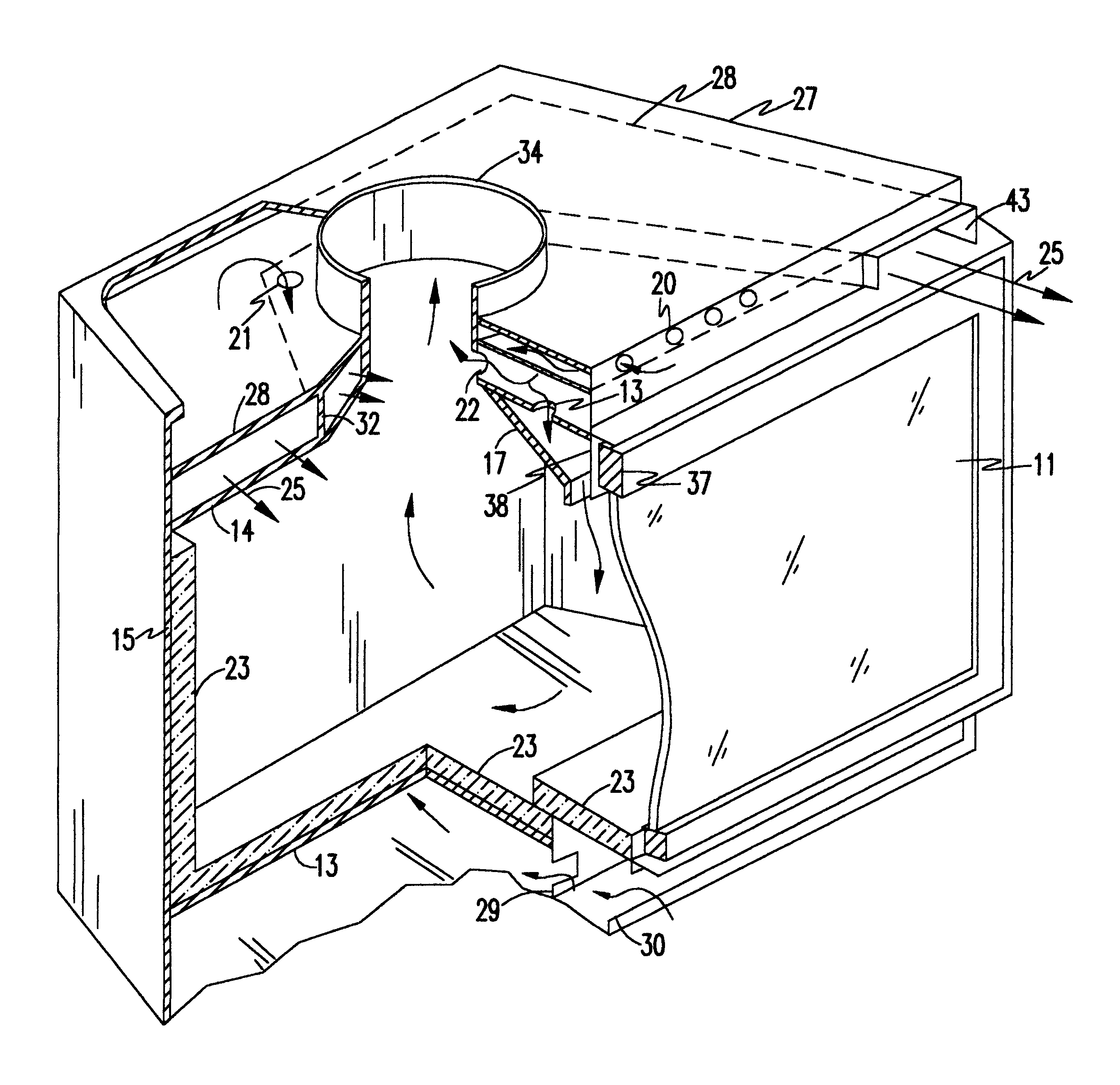
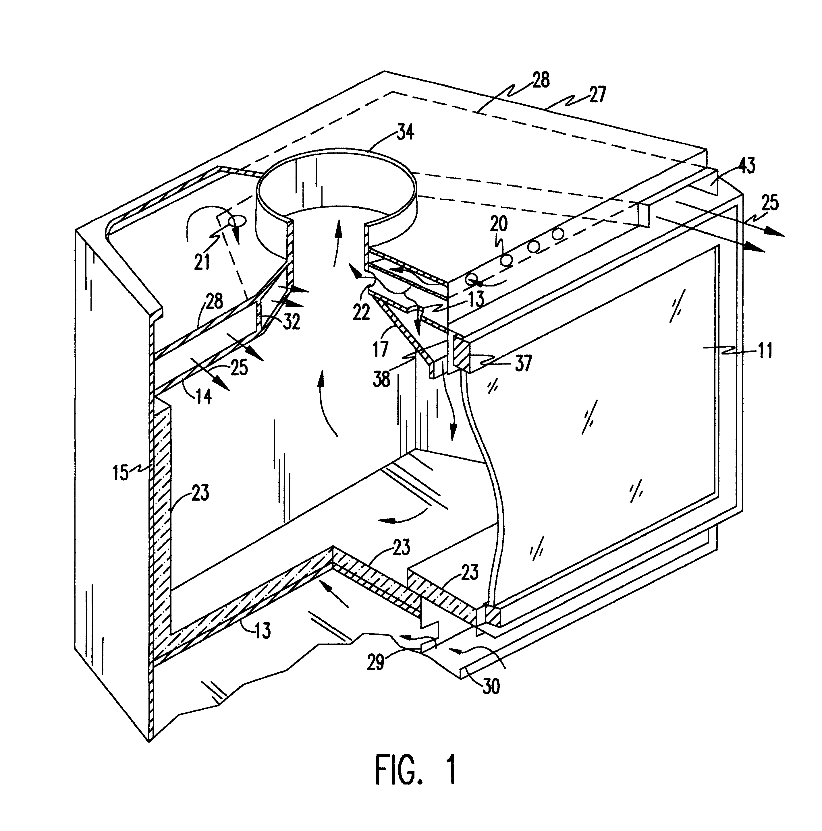
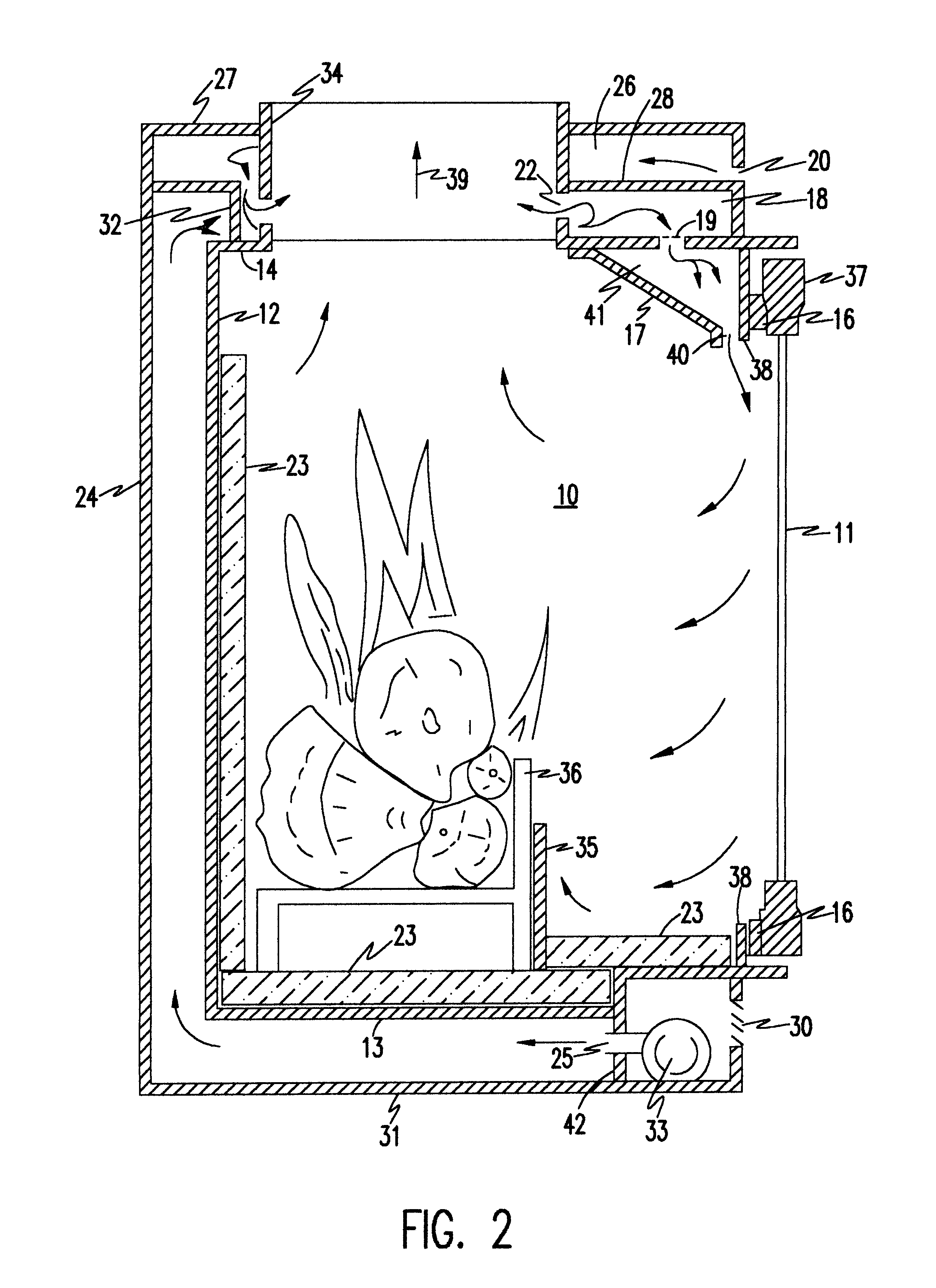
Referring now to the drawings, and more particularly to FIGS. 1 and 2, there are shown a perspective cut away view and a side sectional view of the combustion system of the present invention. In the preferred embodiment, a combustion chamber 10 is defined by vertical front wall 38, rear wall 12 and side walls 15. The bottom and top of the combustion chamber are defined by horizontal panels 13 and 14,respectively. In the...


PUM


Abstract

A combustion system for burning firewood including a combustion chamber defined by front, rear and side walls, a ceiling and a bottom. An access door is provided for addition of fuel into the combustion chamber. A substantial amount of combustion air enters the combustion chamber near the top of the fueling doors via apertures and is directed down the face of the fueling doors providing cooling. A geometry of the air metering orifice is either fixed or of limited adjustability such that the minimum flow of combustion air required for flaming combustion of a full load of fuel is maintained at all times. The combustion air flow cannot be reduced beyond a certain point and thus smoldering and very low air/fuel ratios are avoided. Since the air metering is tuned for proper flaming combustion with the largest expected fuel load and cannot be reduced further, fuel loads smaller than the design fuel load will result in higher air/fuel ratios, thus further ensuring that sufficient combustion air is present for sustained flaming. Furthermore, the minimum combustion air setting limits the amount of combustion air entering the combustion chamber such that too much air is not introduced resulting in inefficiency due to sensible heat loss, chemical loss (pollution), quenching of the flames, and undesirably high burn rates. Ideally, the burning rate of a full load of fuel is below 5 kg/hr, however, the maximum bum rate when burning a full load of fuel may be reduced to as low as 2 kg/hr depending on the size of the firebox and the desired maximum heating capacity of the appliance. Heat output is adjustable primarily by the amount of fuel added at each fuel loading.

Description

1. Field of the InventionThe present invention generally relates to a solid fuel combustion system with improved combustion and aesthetics and, more particularly, to a solid fuel combustion device with a limited travel air supply intended to, amongst other things, simplify operation and reduce emissions of air borne pollutants.2. Background DescriptionIn the mid 1980's growing concern over ambient air quality caused regulators to focus on wood burning appliances as sources of significant amounts of particulate matter and other pollutants which posed a threat to human health. Hardware commonly known as "wood heaters" were the subject of a federal new source performance standard in 1988. This standard required the certification of all new wood heaters sold in the United States and was intended to cover only those products which were capable of burning at low air / fuel mixtures, a condition which can lead to high emissions of particulate matter (PM), carbon monoxide (CO) and other organ...

Claims


Application Information

Patent Timeline
Patent Type & Authority Patents(United States)
IPC IPC(8): F24B5/02F24B5/00
CPCF24B5/026
Inventor CHAMPION, MARK
Owner CHAMPION MARK
Why Eureka
Try Eureka