A further
advantage of the present invention is seen in the method of controlling the operation of the refrigeration system and the cooling of both evaporators thereof. The
control system provides for directing
refrigerant to either of the evaporators as is most efficient. Thus, if the FCB
machine is in a "sleep" mode overnight when no drinks will be dispensed therefrom, the control can direct all the cooling ability if the refrigeration system be utilized to build up the ice
bank at that time. Also, as is known in the art, when the beverage in the cylinder has reached its maximum desired
viscosity, the cooling of the freeze cylinder evaporator must be stopped. Since a semi-frozen beverage can warm quickly to an unacceptably low
viscosity the compressor must then be turned back on. However, and especially where the FCB
machine has more than one freeze cylinder, the compressor can be turned on and off very frequently leading to damaging short
cycling thereof. However, in the present invention, rather than stop the operation of the compressor, the control herein has an option to continue the operation of the compressor to cool the ice bank evaporator if further ice bank growth is needed or can otherwise be accommodated. Thus, when cylinder cooling is again required,
refrigerant can again be directed thereto whereby a short cycling thereof can be avoided. This strategy of being able to alternate cooling between the cylinder evaporators and the ice bank evaporator presents a major
advantage for compressor
longevity, as most, if not all, short cycling can be avoided.
is seen in the method of controlling the operation of the refrigeration system and the cooling of both evaporators thereof. The
control system provides for directing refrigerant to either of the evaporators as is most efficient. Thus, if the FCB machine is in a "sleep" mode overnight when no drinks will be dispensed therefrom, the control can direct all the cooling ability if the refrigeration system be utilized to build up the ice bank at that time. Also, as is known in the art, when the beverage in the cylinder has reached its maximum desired
viscosity, the cooling of the freeze cylinder evaporator must be stopped. Since a semi-frozen beverage can warm quickly to an unacceptably low viscosity the compressor must then be turned back on. However, and especially where the FCB machine has more than one freeze cylinder, the compressor can be turned on and off very frequently leading to damaging short cycling thereof. However, in the present invention, rather than stop the operation of the compressor, the control herein has an option to continue the operation of the compressor to cool the ice bank evaporator if further ice bank growth is needed or can otherwise be accommodated. Thus, when cylinder cooling is again required, refrigerant can again be directed thereto whereby a short cycling thereof can be avoided. This strategy of being able to alternate cooling between the cylinder evaporators and the ice bank evaporator presents a major
advantage for compressor
longevity, as most, if not all, short cycling can be avoided.
A further advantage of the present invention concerns the ability of the
electronic control system thereof to obtain more efficient cooling of the freeze cylinders. The present invention uses a control strategy that can more accurately maintain a pre-selected temperature differential between the inlet and outlet temperatures of the freeze cylinder evaporators. A
control algorithm utilizes a
proportional integral differential control approach that safely permits a much narrower
temperature difference so that a greater length of each freeze cylinder evaporator can be utilized to cool the cylinder contents. Thus, the present invention, by being able to build a cooling reserve and by obtaining better
cooling efficiency from the freeze cylinder evaporators, is able to accomplish more cooling with the same sized refrigeration system found in a comparable prior art machine or can accomplish the same amount of cooling with a smaller refrigeration system.
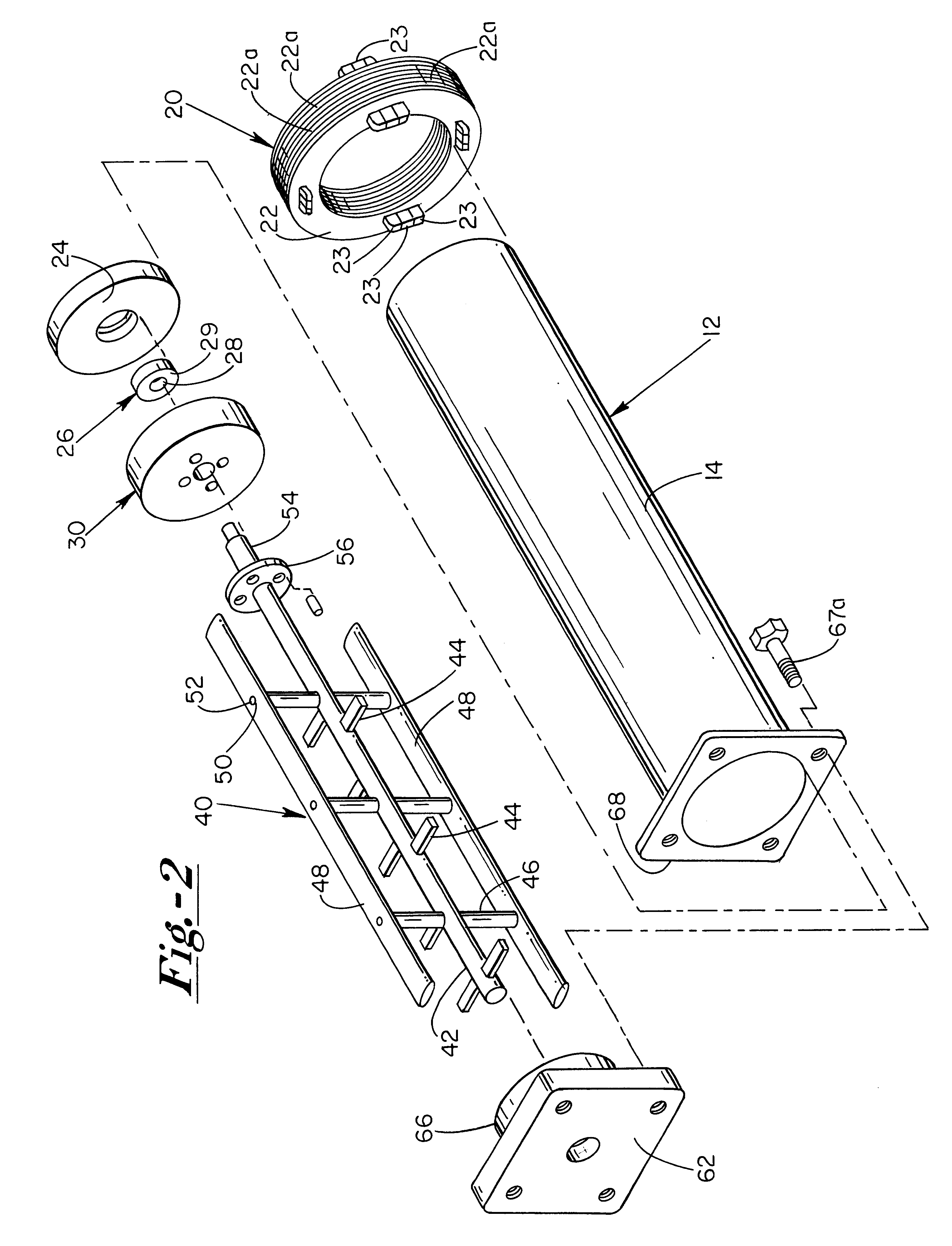
In one preferred embodiment of the present invention, a freeze cylinder is used having a closed end and an open end. Around the cylinder adjacent the closed end a brushless DC
stator is placed. The
stator is connected to a DC power supply (or
inverter). An evaporator is coiled around substantially the remainder of the exterior of the cylinder and connected to a mechanical refrigeration system. A spacer plate holds a bearing centrally thereof and is retained within the cylinder against the closed end thereof. A rotor is positioned in the cylinder adjacent the spacer plate. The rotor consists of
metal ring around the perimeter of which are secured eight permanent magnets. The magnets are equidistantly spaced and alternate as to their polarity. The magnets and disk are encased in a
food grade plastic creating a rotor disk having a central hole. A scraper extends along the axis of the cylinder and includes a central rod end that extends through the rotor and into the bearing of the spacer disk. The scraper includes a skirt portion around the rod end for securing to the rotor. The open end of the cylinder is sealed in the conventional manner with a plate which includes a valve for dispensing beverage from the interior volume of the cylinder and a rotative support for the opposite end of the scraper central rod. A delivery line provides for delivery of the beverage from a source thereof into the cylinder through a beverage inlet fitting.
In operation, it can be understood that the
stator and rotor constitute a brushless DC
three phase motor that is operated by the power supply to rotate the scraper within the cylinder. Those of skill will readily appreciate that no dynamic seal is needed as no rod end of the scraper is required to extend out of the cylinder for mechanical connection to a
drive motor. In addition, prior art machines require a gear case between the actual
drive motor and the scraper rod. This mechanism is also eliminated by the present invention. Accordingly, the present invention provides for a machine that requires less in the way of service calls and that is thereby less expensive to operate. Encasing the rotor in a
food grade plastic permits that portion of the motor to reside within the cylinder thereby making the motor an integral part of the cylinder.
In a further embodiment of the present invention, a freeze cylinder is used that also has a closed end and an open end. A conventional motor and
gear drive are used, however the
gear drive is adapted to rotate a circular magnetic drive plate. The plate includes a plurality of permanent magnets of alternating polarity secured on one surface thereof in a circular arrangement. This external magnetic drive plate is positioned so that the magnetic surface thereof faces and is closely adjacent the exterior surface of the cylinder closed end. Within the cylinder a similar circular magnetic ring is rotatively mounted therein within an annular groove of a stainless steel disk. This internal disk is secured to a rod end of a scraper and the magnetic face of the magnetic ring faces the internal surface of the cylinder end and is positioned closely adjacent thereto. A round plastic collar is secured over the annular groove for sealing the magnetic ring therein.

