Steam turbine, rotor shaft thereof, and heat resisting steel

a technology of steam turbine and rotor shaft, which is applied in the direction of wind motors with perpendicular air flow, waterborne vessels, machines/engines, etc., can solve the problems of inferior high temperature toughness, so as to improve the effect of creep rupture strength and high impact value, and the effect of superior high temperature strength

Inactive Publication Date: 2001-05-01
HITACHI LTD
View PDF39 Cites 26 Cited by
  • Summary
  • Abstract
  • Description
  • Claims
  • Application Information

AI Technical Summary

Benefits of technology

A ratio Mn / Ni or a ratio (Si+Mn) / Ni must be not more than 0.12 and not more than 0.18, respectively, whereby Ni--Cr--Mo--V low alloy steel having a bainitic structure is greatly prevented from being subjected to heating embrittlement, with the result that the low alloy steel is applicable to a rotor shaft integrating low and high pressure portions.
The steel having the characteristics superior in both creep rupture strength and high impact value can be obtained by setting a ratio (V+Mo) / (Ni+Cr) to 0.45 to 0.7, whereby blades each having a length not less than 30 inches can be planted on the rotor shaft integrating high and low pressure portions according to the present invention.
The application of the above new material to a rotor shaft enables long blades having a length of not less than 30 inches to be planted on the rotor shaft as final stage blades, and the rotor shaft can be made compact such that a ratio (L / D) of a length (L) thereof between bearings to a blade diameter (D), is made to 1.4 to 2.3, and preferably the ratio is made to 1.6 to 2.0. Further, a ratio of the maximum diameter (d) of the rotor shaft to a length (l) of final long blades can be made to 1.5 to 2.0. With this arrangement, an amount of steam can be increased to the maximum thereof in accordance with the characteristics of the rotor shaft, whereby a large amount of power can be generated by a small steam turbine. In particular, preferably this ratio is 1.6 to 1.8. A ratio not less than 1.5 is determined from the number of blades, and the greater the ratio, the better the result can be obtained, but preferably the ratio is not more than 2.0 from a view point of strength with respect to a centrifugal force.

Problems solved by technology

The former Cr--Mo--V steel is superior in high temperature strength, but inferior in low temperature toughness.
The latter 3.5 Ni--Cr--Mo--V steel is superior in low temperature toughness, but inferior in high temperature strength.
If the high and low pressure portions are integrated by using the currently available rotor materials, i.e., Cr--Mo--V steel or Ni--Cr--Mo--V steel, the former cannot provide safety against the brittle fracture of the low pressure portion, because it is inferior in low temperature toughness, while the latter cannot provide safety against the creep fracture of the high pressure portion because it is inferior in high temperature strength.
Japanese Patent Laid-open Publication No. 62-189301 discloses a steam turbine integrating high and low pressure portions, which, however, uses a rotor shaft fabricated by mechanically combining a material superior in high temperature strength but inferior in toughness and a material superior in toughness but inferior in high temperature strength, and thus it is not fabricated from a material having the same component.
This mechanical combination requires a large structure to obtain strength and thus the rotor shaft cannot be made small in size and, in addition, the reliability is impaired.

Method used


Image

  • Steam turbine, rotor shaft thereof, and heat resisting steel
  • Steam turbine, rotor shaft thereof, and heat resisting steel
  • Steam turbine, rotor shaft thereof, and heat resisting steel

Examples


example 1

A turbine rotor according to the prevent invention is described below with reference to examples. Table 1 shows chemical compositions of typical specimens subjected to toughness and creep rupture tests, The specimens were obtained in such a manner that they were melted in a high frequency melting furnace, made to an ingot, and hot forged to a size of 30 mm square at a temperature from 850 to 1150.degree. C. The specimens Nos. 1, 3 and 7 to 11 are materials according to the present invention. The specimens Nos. 2, 4 to 6 were prepared for the comparison with the invented materials. The specimen No. 5 is a material corresponding to ASTM A470 Class 8 and the specimen No. 6 is a material corresponding to ASTM A470 Class 7. These specimens were quenched in such a manner that they were made to have austenitic structure by being heated to 950.degree. C. in accordance with a simulation of the conditions of the center of a rotor shaft integrating high and low pressure portions of a steam tur...

example 2

Table 5 shows typical chemical compositions (wt %) of specimens used in an experiment.

The specimens were obtained in such a manner that they were melted in a high frequency melting furnace, made to an ingot, and hot forged to a size of 30 mm square at a temperature from 850 to 1250.degree. C. The specimens Nos. 21 and 22 were prepared for the comparison with the invented materials. The specimens Nos. 23 to 32 are rotor materials superior in toughness according to the present invention.

The specimens Nos. 23 to 32 were quenched in such a manner that they were austenitized being heated to 950.degree. C. in accordance with a simulation of the conditions of the center of a rotor shaft integrating high and low pressure portions of a steam turbine, and then cooled at a speed of 100.degree. C. / h. Next, they were annealed by being heated at 650.degree. C. for 50 hours and cooled in a furnace. Cr--Mo--V steel according to the present invention included no ferrite phase and was made to have a ...

example 3

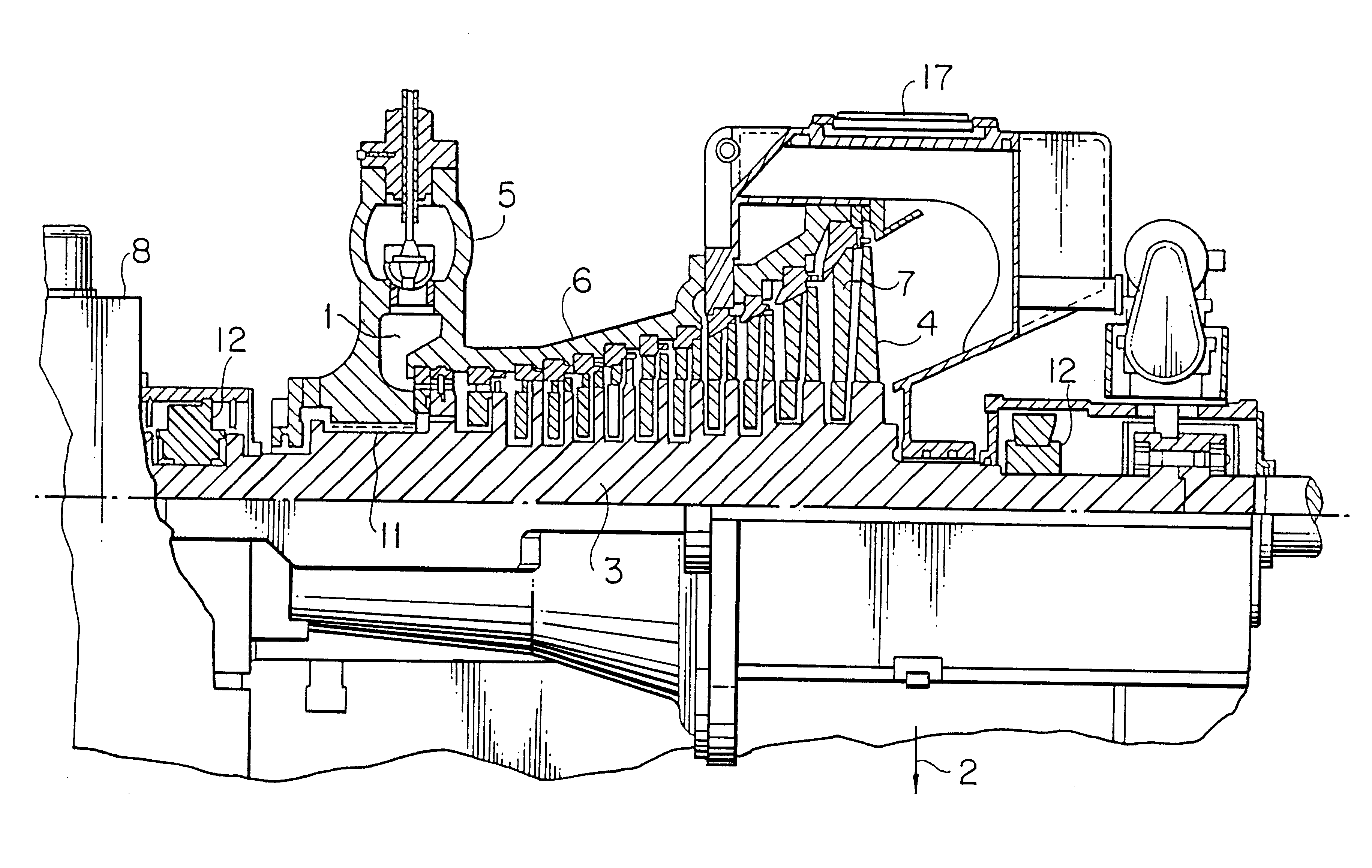
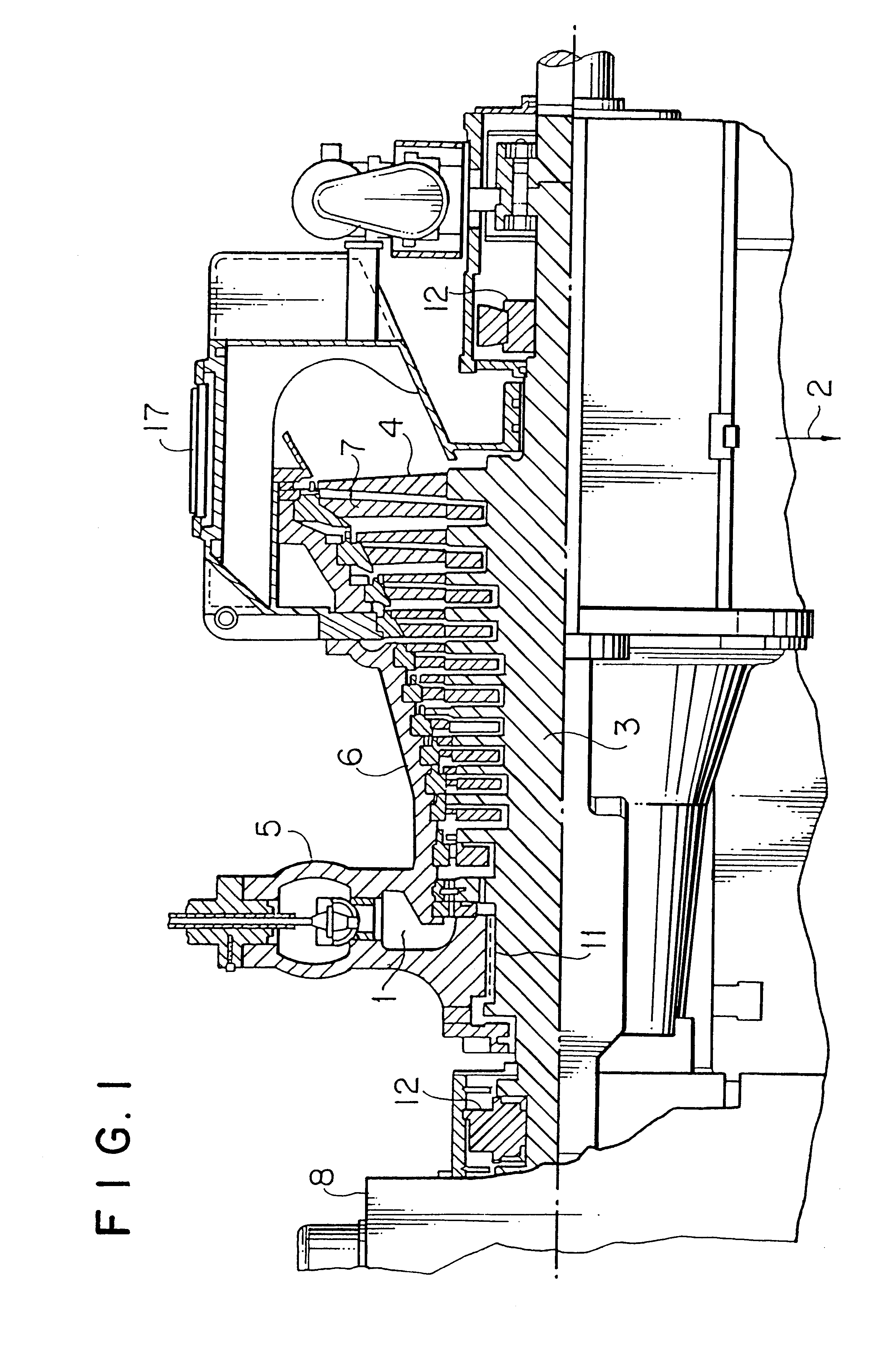
FIG. 1 shows a partial cross sectional view of a non-reheating type steam turbine integrating high and low pressure portions according to the present invention. A conventional steam turbine consumes high pressure and temperature steam of 80 atg and 480.degree. C. at the mein steam inlet thereof and low temperature and pressure steam of 722 mmHg and 33.degree. C. at the exhaust portion thereof by a single rotor thereof, whereas the steam turbine integrating high and low pressure portions of the invention can increase an output of a single turbine by increasing a pressure and temperature of steam at the main steam inlet thereof to 100 atg and 536.degree. C., respectively. To increase an output of the single turbine, it is necessary to increase a blade length of movable blades at a final stage and to increase a flow rate of steam. For example, when a blade length of the movable blade at a final stage is increased from 26 inches to 33.5 inches, an ring-shaped band area is increased by a...


PUM


Abstract

A steam turbine comprising a rotor shaft integrating high and low pressure portions provided with blades at the final stage thereof having a length not less than 30 inches, wherein a steam temperature at first stage blades is 530° C., a ratio (L/D) of a length (L) defined between bearings of the rotor shaft to a diameter (D) measured between the terminal ends of final stage blades is 1.4 to 2.3. This rotor shaft is composed of heat resisting steel containing by weight 0.15 to 0.4% C, not more than 0.1% Si, 0.05 to 0.25% Mn, 1.5 to 2.5% Ni, 0.8 to 2.5% Cr, 0.8 to 2.5% Mo and 0.15 to 0.35% V and, further, the heat resisting steel may contain at least one of Nb, Ta, W, Ti, Al, Zr, B, Ca, and rare earth elements.

Description

1. Field of the InventionThe present invention relates to a novel steam turbine, and more specifically, to a steam turbine provided with a rotor integrating high and low pressure portions fabricated from Ni--Cr--Mo--V low alloy steel having superior high temperature strength and toughness, the rotor shaft thereof, heat resisting steel, and a manufacturing method thereof.2. Description of the Prior ArtIn general, Cr--Mo--V steel specified in accordance with ASTM (Designation: A470-84, Class 8) is used as a material of a high pressure rotor exposed to high temperature steam (steam temperature: about 538.degree. C.) and 3.5 Ni--Cr--Mo--V steel specified in accordance with ASTM (Designation: A470-84, Class 7) is used as a material of a low pressure (steam temperature: about 100.degree. C.) rotor. The former Cr--Mo--V steel is superior in high temperature strength, but inferior in low temperature toughness. The latter 3.5 Ni--Cr--Mo--V steel is superior in low temperature toughness, but ...

Claims


Application Information

Patent Timeline
Patent Type & Authority Patents(United States)
IPC IPC(8): C22C38/48C22C38/44C22C38/46C21D9/38F01D5/02F01D5/28F01D5/14F01D5/06
CPCC21D9/38C22C38/44C22C38/46C22C38/48F01D5/02F01D5/06F01D5/141F01D5/147F01D5/28F01D5/288C21D2211/002F05D2300/171F05D2300/133
Inventor SIGA, MASAOFUKUI, YUTAKAKURIYAMA, MITSUOMAENO, YOSHIMISUWA, MASATERUKANEKO, RYOICHIONODA, TAKESHIKAJIWARA, HIDEFUMIWATANABE, YASUOTAKAHASHI, SHINTAROTAN, TOSHIMI
Owner HITACHI LTD
Why Eureka
Try Eureka