Combustion apparatus

a technology of combustion apparatus and combustion chamber, which is applied in the direction of combustion type, combustion using catalytic material, lighting and heating apparatus, etc., can solve the problems of reducing service life remarkably, difficult to stably perform the inconsistent operation of cooling, and reducing reaction at the first stag

Inactive Publication Date: 2001-05-01
PANASONIC CORP
View PDF19 Cites 20 Cited by
  • Summary
  • Abstract
  • Description
  • Claims
  • Application Information

AI Technical Summary

Problems solved by technology

However, if the catalytic combustion apparatus is operated with the same combustion intensity (combustion amount per combustion chamber volume) as that of the flame combustion apparatus, the catalyst body temperature reaches 1200.degree. C. or higher, exceeding the heat resistance limit of catalyst, so that the service life is decreased remarkably.
However, it is difficult to stably perform the inconsistent operation in which cooling is performed while heat is stably generated by a catalyst.
If cooling is excessive, the combustion reaction at the first stage decreases, so that high-concentration unburned gas slips to the downstream side.
When the second-stage catalyst exists, the combustion therein becomes excessive, so that the second-stage catalyst exceeds the heat resistance limit temperature.
From this viewpoint as well, it is found that it is an important problem to stabilize the first-stage catalytic combustion by properly setting the heating and cooling in the combustion section and to maintain the catalyst temperature at a proper value.
However, this method is contrary to the trend of downsizing of equipment.
Also, because the catalytic combustor has a construction in which elements are packed in the combustion chamber, it is difficult in the catalytic combustion system to use a configuration such that a water passage is arranged around the combustion chamber, this configuration being often used in the flame combustion system.
However, there arises a problem in that preheating takes much time because the heater itself has a heat capacity, and the rise time is longer than that of the flame combustion.
The long rise time caused by the use of electric heater for preheating leads to an increase in electric power consumption, with the result of impaired energy saving.
More specifically, since the heat transfer at this portion is effected between the catalyst body surface and the fin in the heat receiving section, the mutual relationship between the two, for example, position or material acts delicately.
Because the catalytic combustor has a configuration such that many elements are packed in a combustion chamber (so called in the flame combustor), it was difficult to provide a configuration such that a housing is surrounded by a water passage.

Method used


Image

  • Combustion apparatus
  • Combustion apparatus
  • Combustion apparatus

Examples


second embodiment

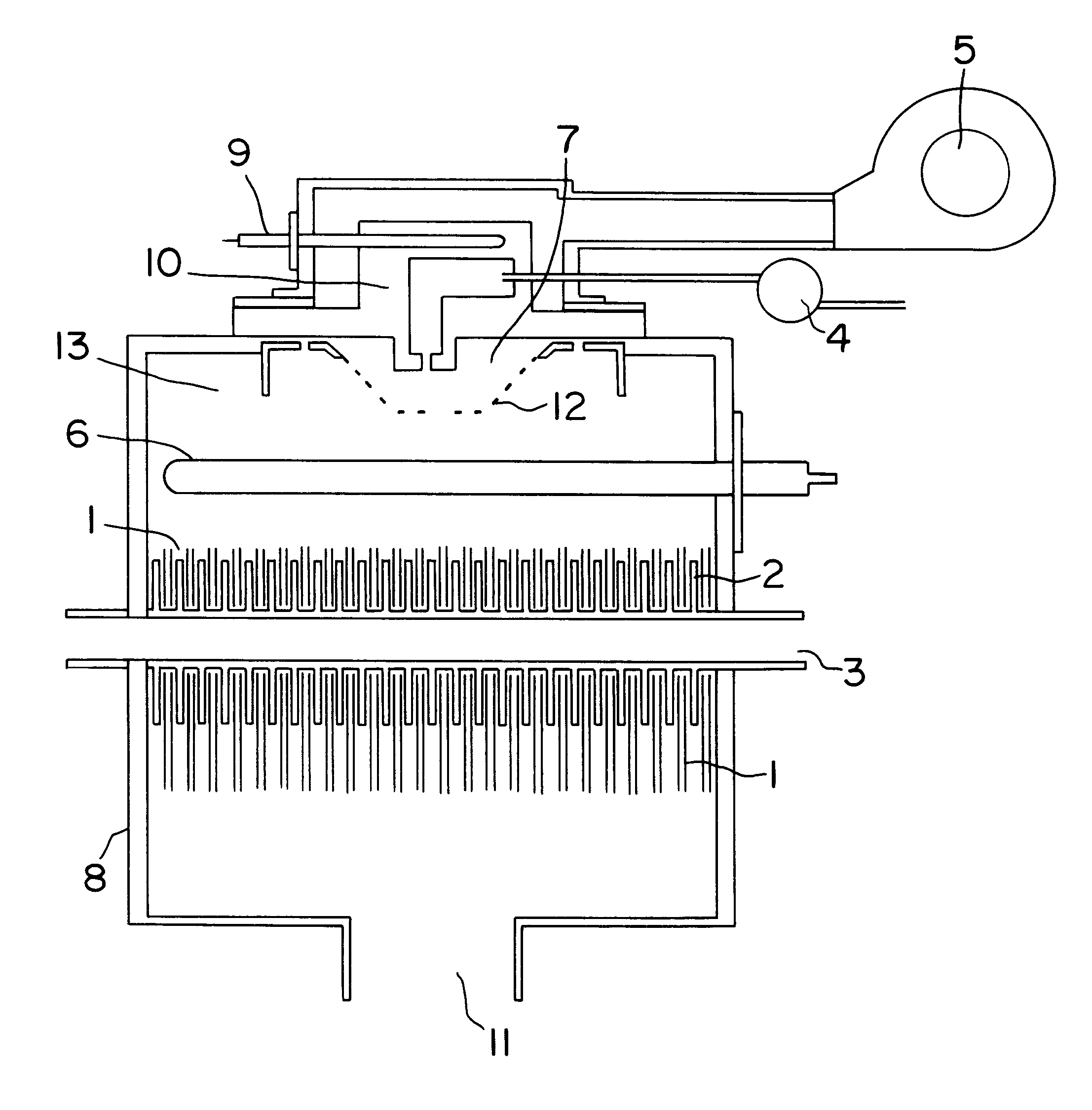
FIG. 10 is a sectional view of a principal portion showing a combustion apparatus in accordance with the present invention. The same elements as those shown in FIG. 1 are shown by the same reference numerals, and the explanation thereof is omitted. In this embodiment, a mixing unit 25 is formed by the fuel supply section 4, the air blowing section 5 for supplying combustion air, and the mixing section 7 for mixing fuel with air. Also, a heat receiving section consisting of the catalyst bodies 1 and the heat receiving fins 2 is provided in a housing 27 which consists of double walls and is formed with a heat medium passage 26 between the double walls, so that the cooling path 3 is made to communicate with the heat medium passage 26 of the housing 27. Reference numeral 28 denotes a sealing material for connecting the mixing unit 25 to the housing 27. The unitization provides easy assembly and maintenance. The use of a heat insulating material as the sealing material 28 prevents the mo...

third embodiment

FIG. 11 is a sectional view of a principal portion showing a combustion apparatus in accordance with the present invention. This embodiment is so configured that second catalyst bodies are provided on the downstream side of the catalyst bodies 1 and a second heat receiving section is provided on the downstream side of the second catalyst bodies. The same elements as those shown in FIG. 1 are shown by the same reference numerals, and the explanation thereof is omitted. Reference numeral 31 denotes the second catalyst body configured by carrying a precious metal catalyst on a ceramic honeycomb carrier with high air permeability. Two sheets of second catalyst body are provided, and an electric heater 36 for preheating catalyst is provided therebetween. Reference numeral 33 denotes a combustion chamber, and 34 denotes a heat insulating material provided inside the housing 38. The cooling path 3 penetrates both of the heat receiving section consisting of the catalyst bodies 1 and the lik...

fourth embodiment

FIG. 12 is a sectional view of a principal portion showing a combustion apparatus in accordance with the present invention. In this embodiment, the whole equipment is unitized. The principal portion is configured by four units; a mixing unit 51 for mixing fuel with combustion air, a first catalyst unit 52 formed by a heat receiving section consisting of the catalyst bodies 1 and the heat receiving fins 2 and a first housing 45 which consists of double walls and is formed with a heat medium passage between the double walls, a second catalyst unit 53 configured by the second catalyst bodies 31 and the electric heater 36 for heating, and a heat recovery unit 54 formed by the second heat receiving section 32 and a second housing 46 which consists of double walls and is formed with a heat medium passage between the double walls. To join the four units in the order of the mixing unit 51, the first catalyst unit 52, the second catalyst unit 53, and the heat recovery unit 54, sealing materi...


PUM


Abstract

A combustion apparatus has a fuel supply section; an air blowing section for supplying combustion air; a mixing section for mixing the fuel with the combustion air; a plurality of first catalyst bodies which are arranged substantially in parallel with each other to divide the downstream location in the flow direction of mixture into a plurality of flow paths; and a first heat receiving section configured by a plurality of heat receiving fins arranged in flow paths divided by said first catalyst bodies and a cooling path penetrating the heat receiving fins, the opposed heat receiving fin and first catalyst body being characterized in that the area of the heat receiving fin on the upstream side of said cooling path is smaller than the area of the first catalyst body on the upstream side of the cooling path.

Description

1. Field of the InventionThe present invention relates to a combustion apparatus for a heating apparatus used for a heater, hot water supply system, air conditioner, and the like.2. Related Art of the InventionIn place of the conventional combustion apparatus forming flame, a catalytic combustion apparatus has been proposed in which the emission of nitrogen oxides is greatly reduced and the exhaust gas is made clean. However, if the catalytic combustion apparatus is operated with the same combustion intensity (combustion amount per combustion chamber volume) as that of the flame combustion apparatus, the catalyst body temperature reaches 1200.degree. C. or higher, exceeding the heat resistance limit of catalyst, so that the service life is decreased remarkably.As a means to solve this problem of combustion intensity, as shown, for example, in one embodiment of Japanese Patent Application No. 7-316888 shown in FIG. 16. a combustion system is available which is made up of a first cata...

Claims


Application Information

Patent Timeline
Patent Type & Authority Patents(United States)
IPC IPC(8): F24H1/40F23C13/00F23M9/10F24H1/22F24H1/00F23M9/00F23C99/00F24H9/00
CPCF23C13/00F23C13/02F23M9/10F24H1/0045F24H1/40
Inventor TOMIZAWA, TAKESHIFUJITA, TATSUOMAENISHI, AKIRASUZUKI, JIROOHARA, KATUYUKI
Owner PANASONIC CORP
Why Eureka
Try Eureka