Micro-magnetohydrodynamic pump and method for operation of the same

a technology of magnetohydrodynamic pump and pump body, which is applied in the direction of pump components, positive displacement liquid engine, piston pump, etc., can solve the problems of difficult integration, inability to implement a complete mechanical system, and inability to fully realize the mechanical system

Inactive Publication Date: 2001-06-05
RGT UNIV OF CALIFORNIA
View PDF8 Cites 45 Cited by
  • Summary
  • Abstract
  • Description
  • Claims
  • Application Information

AI Technical Summary

Problems solved by technology

Since micromachined sensors are passive devices, a complete mechanical system is not readily implemented.
In order to complete the system, actuators, namely machines that cause other devices to move, are badly needed.
However, due to t

Method used


Image

  • Micro-magnetohydrodynamic pump and method for operation of the same
  • Micro-magnetohydrodynamic pump and method for operation of the same
  • Micro-magnetohydrodynamic pump and method for operation of the same

Examples


Embodiment Construction

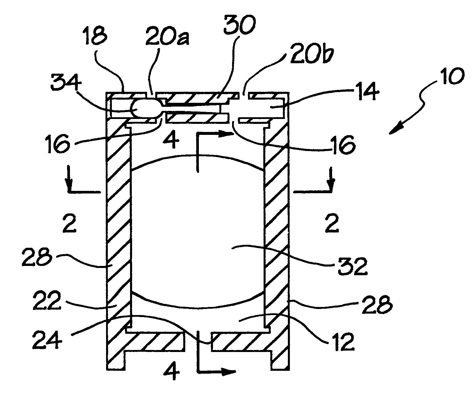
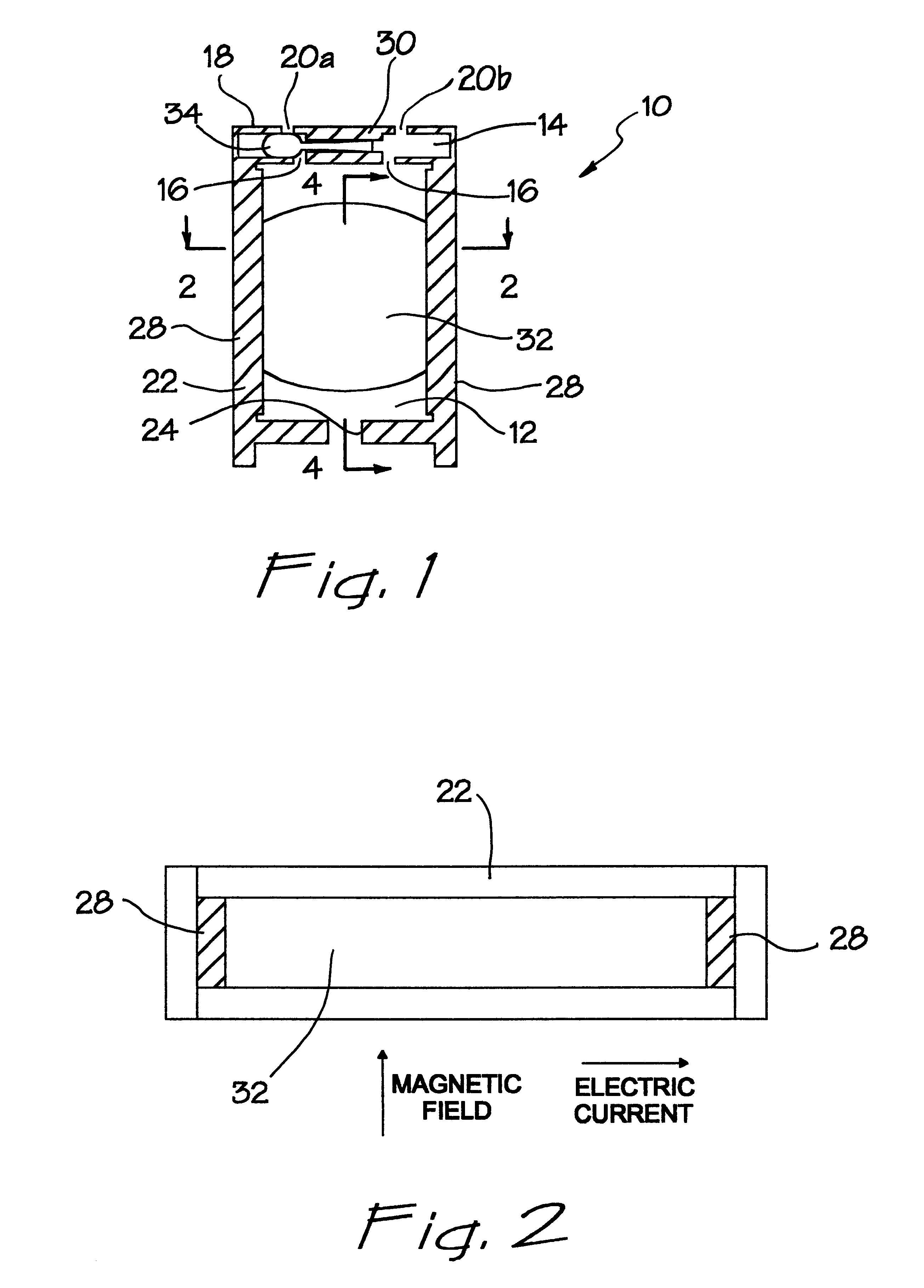
, consider first some of its advantageous features. A first feature of the present invention is the fabrication of the micropump 10 using a planar manufacturing process, which allows miniaturization and mass manufacture of the device using conventional silicon micromachining techniques and integration with other micromachined and circuit components on the same substrate. For example, pump 10 may be fabricated so that the embodiment of FIG. 1 is entirely circumscribed in a volume of 1.times.1.times.5 mm. As a result of using a liquid metal or a conducting liquid, the micropump 10 has a reliable means for pumping that is sufficiently small in size. In the illustrated embodiment, the mechanism which converts electrical energy to mechanical energy is implemented by a combination using liquid metal pistons 32 and 34. The liquid metal pistons 32 and 34 not only facilitate the action of pumping, but also ensures the opening and closing of the flow passages to and from the main pumping cham...


PUM


Abstract

A micropump fabricated in a planar substrate is provided with a valving chamber which is communicated to a pumping chamber. The valving chamber has an inlet and outlet port. Both the valving chamber and pumping chamber have a liquid, electrically conductive piston disposed therein, which liquid piston is nonmiscible with the pumped working fluid and nonreactive with the substrate in which the chambers are formed. The valving piston is magnetohydrodynamically driven to selectively close either the inlet port or the outlet port. The pumping piston is magnetohydrodynamically driven to pull or push the working fluid through one of the inlet or outlet ports, through the valving chamber, into the pumping chamber, back out of the pumping chamber and through the other one of the inlet or outlet ports after activation of the valving piston. Both direct current and inductive magnetohydrodynamic drives are contemplated. The valving and/or pumping chambers may be shaped or narrowed in their dimensions to impose a mechanical bias on the respective valving and/or pumping pistons to assume a preferred position in their respective chambers when the magnetohydrodynamic drive is turned off.

Description

1. Field of the InventionThe present invention relates to a micropump for delivering fluid at a low and controllable flow rate.2. Description of the Prior ArtScience and engineering have been devoted to building machines that mimic human's functionality to expand our reach. The Industrial Age came about due to the invention of steam engine which freed human from laborious muscle works. With the advent of electronics, computers are revolutionizing the Information Age. Advances in microelectronics processing have opened up a far reaching capabilities in microengineering.In recent years, there has been an explosion of interest in the field of integrated MicroElectroMechanical Systems (MEMS). The field is still so new that there is no commonly accepted definition of the field among researchers. Instead of fashioning devices that simply shunt electrons, moving devices are fabricated. While integrated circuit technology is essentially a two-dimensional or planar process. MEMS works in a t...

Claims


Application Information

Patent Timeline
IPC IPC(8): F04B7/00F04B17/04F04B17/03F04B19/00F04F11/00F04F99/00
CPCF04B7/00F04B17/044F04B19/006F04F99/00
Inventor CHU, CHARLES YE YINGJIELI, GUANN PYNG
Owner RGT UNIV OF CALIFORNIA
Why Eureka
Try Eureka