Explosion-proof seal plate for enclosed type cell and production method thereof

a technology of enclosed type cells and seal plates, which is applied in the direction of cell components, electrical equipment, cell component details, etc., can solve the problems of large dispersion of weld strength, inability to set to a fixed value, and excessive pressure inside the cell,

Inactive Publication Date: 2001-06-05
PANASONIC CORP
View PDF6 Cites 30 Cited by
  • Summary
  • Abstract
  • Description
  • Claims
  • Application Information

AI Technical Summary

Problems solved by technology

On the other hand, sealed batteries with a high energy density tend to generate abnormal gas inside the cells due to chemical reaction resulting from troubles in associated equipment including the charger or from over charge or erroneous use, thus causing an excessive pressure inside cells, explosion of cells, or damage to the electronic equipment using the cells as the power supply.
Furthermore, as non-aqueous electrolyte secondary batteries have a danger of ignition due to a rapid temperature rise, they are equipped with a reliable safety mechanism against explosion which will completely cut off electric current prior to exhausting gas by detecting the internal pressure.
However, since ultrasonic welding causes fusion by vibration heating only on the surface of the work piece, there is a possibility of causing a large dispersion in the weld strength.
Consequently, in the above-described explosion-proof safety mechanism, as the pressure of cutting off an electric current is determined dependent on the weld strength of the welded portion, the pressure of cutting off an electric current varies with the variability of the weld strength, exhibiting a drawback of not being able of setting to a fixed value.
As a result, it suffers problems of cutting off an electric current before the cell internal pressure rises to a predetermined value, or not cutting off an electric current even when the cell internal pressure has risen to a predetermined value.

Method used


Image

  • Explosion-proof seal plate for enclosed type cell and production method thereof
  • Explosion-proof seal plate for enclosed type cell and production method thereof
  • Explosion-proof seal plate for enclosed type cell and production method thereof

Examples


first exemplary embodiment

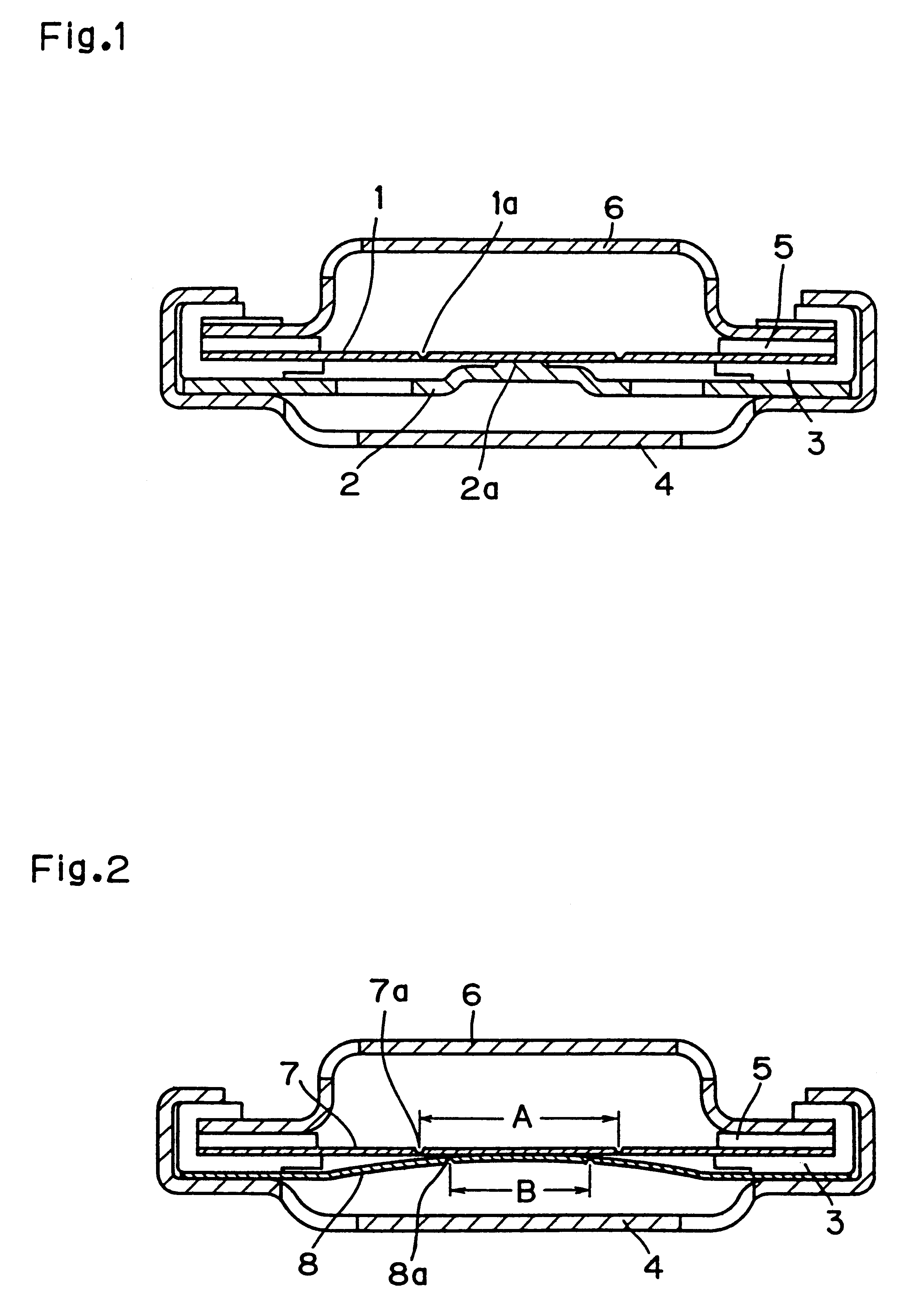
FIG. 1 shows the construction of a seal plate in accordance with the first exemplary embodiment of the present invention, wherein a thin portion 1a is provided in the central portion of an upper metallic foil 1 made of aluminum with a thickness of 0.15 mm and a diameter of 12.7 mm using a C-shaped stamping die having a diameter of 4.0 mm, a protrusion 2a with a diameter of 1.0 mm is provided in the center of a lower metallic foil 2 made of aluminum with a thickness of 0.3 mm and a diameter of 13.5 mm and having 4 vent holes of 1.5 mm diameter, and the two metallic foils were welded by ultrasonic welding at the central portion of the upper metallic foil 1 and the protrusion 2a of the lower metallic foil 2 with an insulating gasket 3 interposed. They were then encased in a metallic case 4 made of aluminum and having 4 vent holes of 1.5 mm diameter, a temperature dependent resistor 5 and a metallic cap 6 having 4 vent holes of 1.5 mm diameter were placed on top of it, and then the peri...

second exemplary embodiment

FIG. 2 shows the construction of a seal plate in accordance with the second exemplary embodiment of the present invention, wherein a thin portion 7a is provided in the central portion of an upper metallic foil 7 made of aluminum with a thickness of 0.10 mm and a diameter of 12.7 mm using a C-shaped stamping die having a diameter of 4.0 mm, a thin portion 8a is provided on a lower metallic foil 8 made of aluminum with a thickness of 0.10 mm and a diameter of 13.5 mm and having 4 vent holes of 1.5 mm diameter using an O-shaped stamping die having a diameter of 2.5 mm, and the two metallic foils were welded by ultrasonic welding at the central portions of the two metallic foils with an insulating gasket 3 interposed. Here the breaking strength of the thin portion 8a of the lower metallic foil 8 was 10-13 kg / cm.sup.2 while the breaking strength of the thin portion 7a of the upper metallic foil 7 was 18-24 kg / cm.sup.2. They were then encased in a metallic case 4 made of aluminum and havi...

third exemplary embodiment

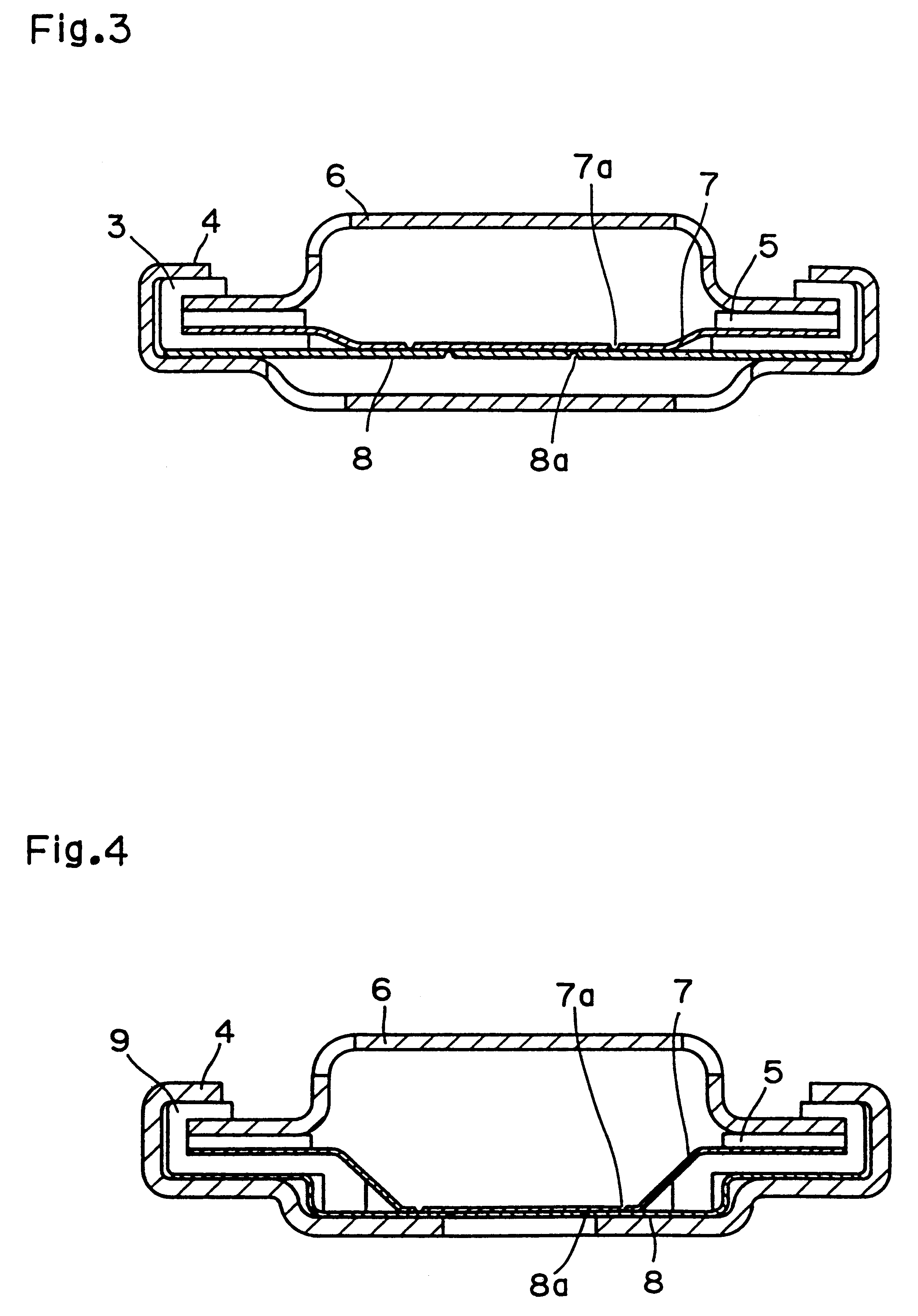
FIG. 3 shows the construction of a seal plate in accordance with the third exemplary embodiment of the present invention, wherein a thin portion 7a is provided in the central portion of an upper metallic foil 7 made of aluminum with a thickness of 0.10 mm and a diameter of 12.7 mm by using a C-shaped stamping die having a diameter of 4.0 mm, the central portion of the upper metallic foil 7 is made lower by 0.5 mm below its peripheral in the form of a reversed trapezoid, a thin portion 8a is provided on a lower metallic foil 8 made of aluminum with a thickness of 0.10 mm and a diameter of 13.5 mm and having 4 vent holes of 1.5 mm diameter using an O-shaped stamping die having a diameter of 2.5 mm, an insulating gasket 3 was interposed between the peripheries of the two metallic foils, and the central portion in the form of a reversed trapezoid of the upper metallic foil 7 and the central portion of the lower metallic foil were welded. They were then encased in a metallic case 4 made ...


PUM

PropertyMeasurementUnit
diameteraaaaaaaaaa
thicknessaaaaaaaaaa
thicknessaaaaaaaaaa

Abstract

The present invention relates to an explosion-proof seal plate for a sealed cell and a production method thereof and aims at providing an explosion-proof seal plate and production method thereof, wherein problems of a risk of explosion of a cell due to an excessive pressure inside the cell caused by abnormal generation of a gas through a chemical reaction accompanying over charge or erroneous use of the cell or damaging of electronic equipment using the cell as the power source are solved, ignition and other accidents can be prevented with a high accuracy by reliably cutting off an electric current when the cell internal pressure increases, and the increase in the resistance due to permeation of an electrolyte can be limited. In order to accomplish this aim, the present invention provides a thin portion 7a having a breaking strength of 18-24 kg/cm2 in the central portion of an upper metallic foil 7 made of aluminum and a thin portion 8a having a breaking strength of 10-13 kg/cm2 in the central portion of a lower metallic foil 8 made of aluminum, wherein the diameter A of the thin portion 7a of the upper metallic foil and the diameter B of the thin portion 8a of the lower metallic foil 8 satisfy the relation AB. The two metallic foils are welded at the central portions with an insulating gasket interposed, and encased in a metallic case 4 made of aluminum having 4 vent holes, on top of which a temperature dependent resistor 5 and a metallic cap 6 having 4 vent holes are then placed. A seal plate is obtained by sealing the periphery of the metallic case 4, with which it is possible to prevent accidents such as ignition and explosion of a cell by reliably allowing internal gas to exhaust in the event of generation of a large volume of gas under an abnormal condition of a sealed cell.

Description

This invention relates to explosion-proof top assemblies for sealed cells to be used in sealing sealed cells, especially high energy density cells such as lithium secondary cells, and their method of producing.BACKGROUND OF THE TECHNOLOGYIn recent years, there has been rapid progress in portable and / or cordless designs of audiovisual equipment, personal computers and other electronic equipment. As the power supply for these electronic equipment, high capacity type of non-aqueous electrolyte secondary batteries such as represented by various alkaline storage batteries and lithium secondary batteries are suitable. These non-aqueous electrolyte secondary batteries are desired to be implemented as sealed batteries with a high energy density and with superior load characteristics.On the other hand, sealed batteries with a high energy density tend to generate abnormal gas inside the cells due to chemical reaction resulting from troubles in associated equipment including the charger or fro...

Claims


Application Information

Patent Timeline
Patent Type & Authority Patents(United States)
IPC IPC(8): H01M2/34H01M2/20H01M2/12H01M50/574
CPCH01M2/1235H01M2/1241H01M2/34H01M2/345Y02E60/10H01M50/342H01M50/3425H01M50/578H01M50/574
Inventor MORI, KATSUHIKOKASHIHARA, YOSHIHIROHIRAKAWA, YASUSHISAITO, KAZUOWATANABE, KAZUHIKO
Owner PANASONIC CORP
Why Eureka
Try Eureka