Continuous metal fiber brushes

a technology of fiber brushes and fibers, applied in the field offiber brushes, can solve the problems of shortening the service interval, reducing the service life of brushes, and reducing the heat dissipation

Inactive Publication Date: 2001-06-12
VIRGINIA UNIV PATENT FOUND OF
View PDF26 Cites 58 Cited by
  • Summary
  • Abstract
  • Description
  • Claims
  • Application Information

AI Technical Summary

Benefits of technology

The open end of the cylinder may be shaped to conform, with a predetermined clearance (12), to the running surface on which the brush slides, e.g. slip ring, commutator or rail (15). Similarly, a guide may be used in conjunction with bellows. Depending on conditions, e.g. in connection with fast-moving vehicles, it may be advantageous to make that clearance small so as to shield the brush from wind forces. Similarly, in motors or generators, it may

Problems solved by technology

This translates to extremely long brush life and greatly lengthened service intervals.
Because they operate at low loads and have very low resistance, metal fiber brushes dissipate much less heat than typical brushes in high-curren

Method used


Image

  • Continuous metal fiber brushes
  • Continuous metal fiber brushes
  • Continuous metal fiber brushes

Examples


Embodiment Construction

a. General Considerations

The previous metal fiber brushes suffered from the following problems;

difficulty of manufacture

limitations on the achievable relationship between macroscopic brush stiffness and microscopic fiber compliance

problems associated with the necessity of using a removable constituent during manufacturing

limitations on the types of metals usable as conductors in the brushes on account of the need for differential etchability or dissolution of the matrix material.

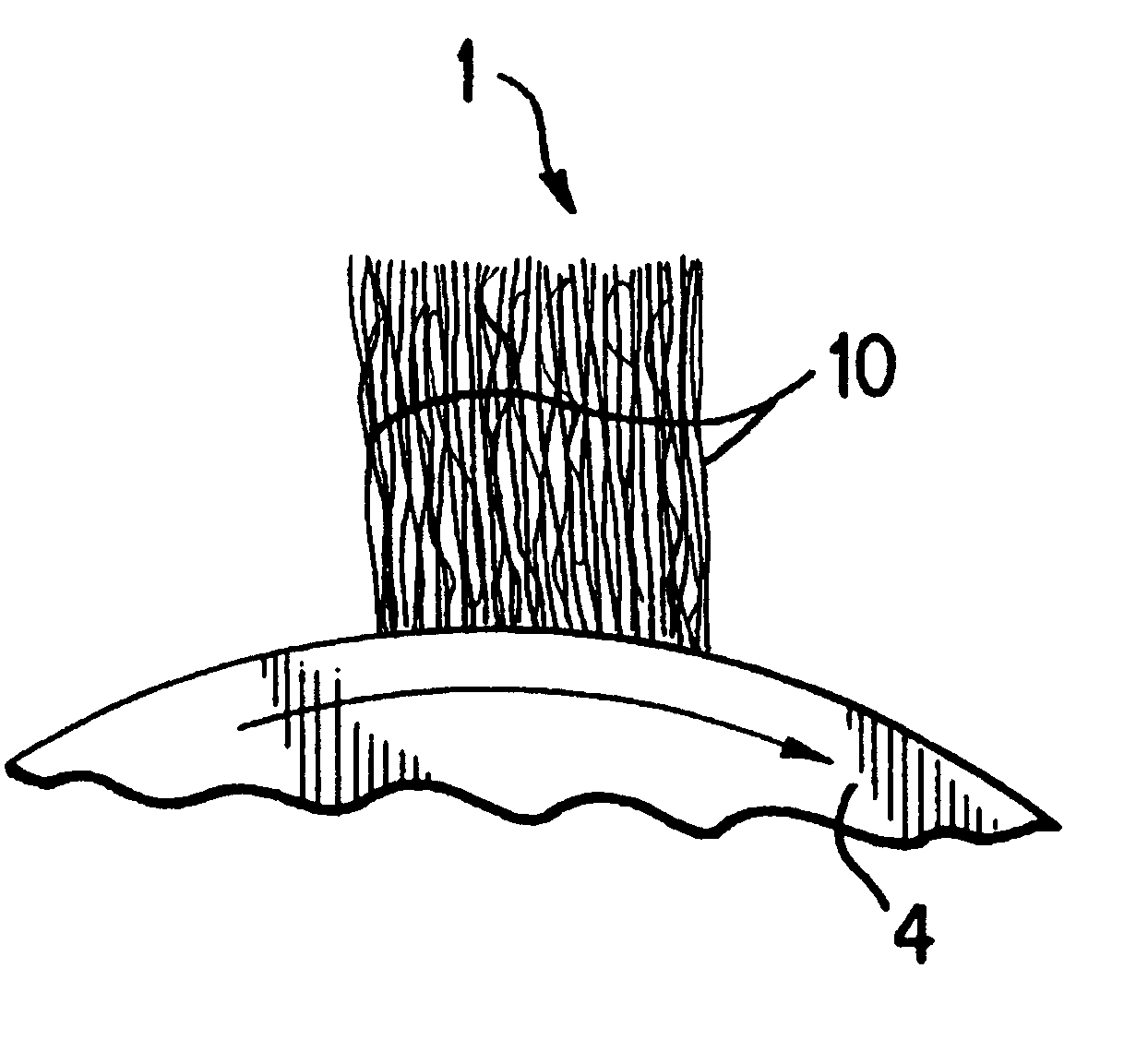
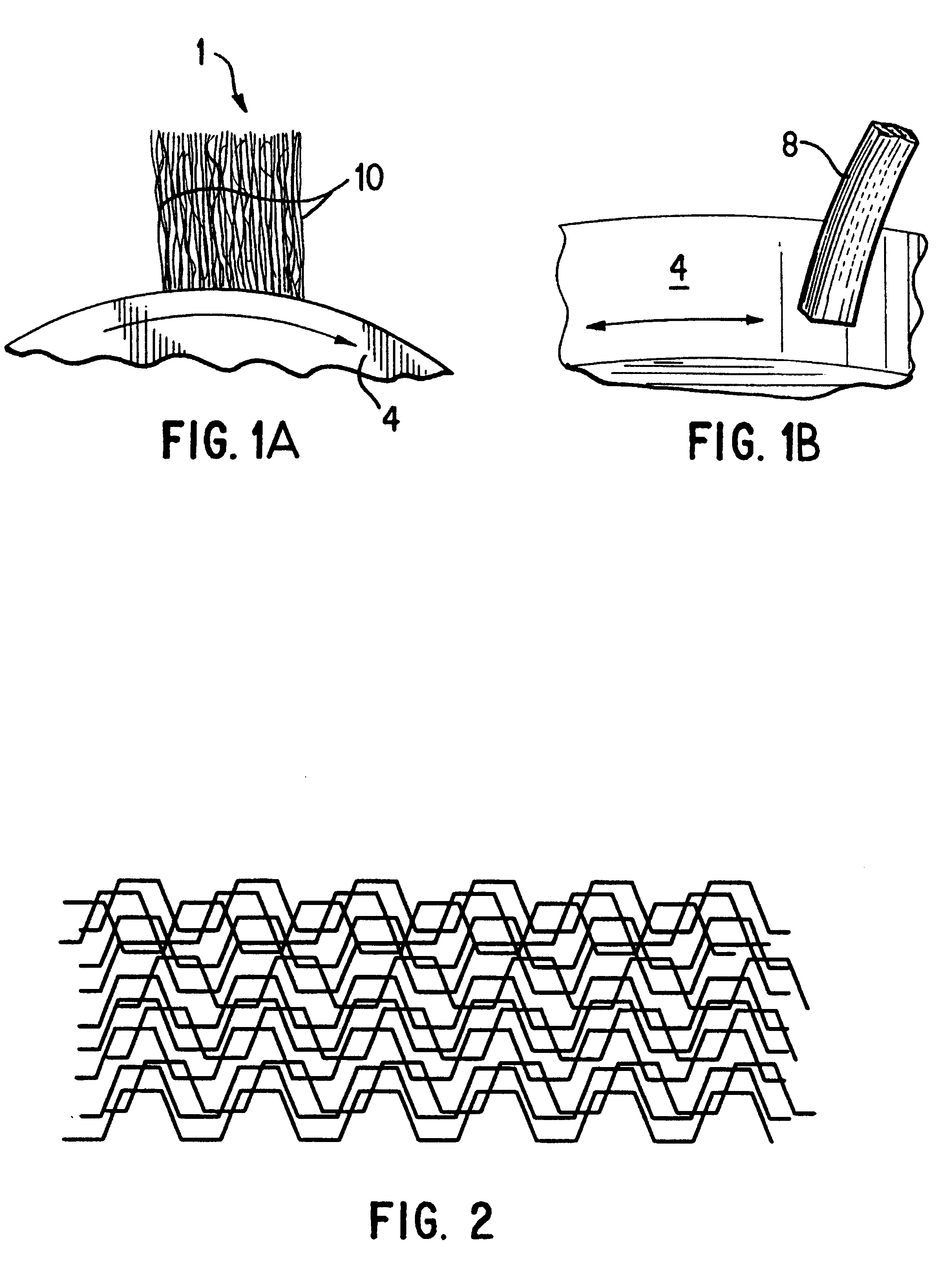
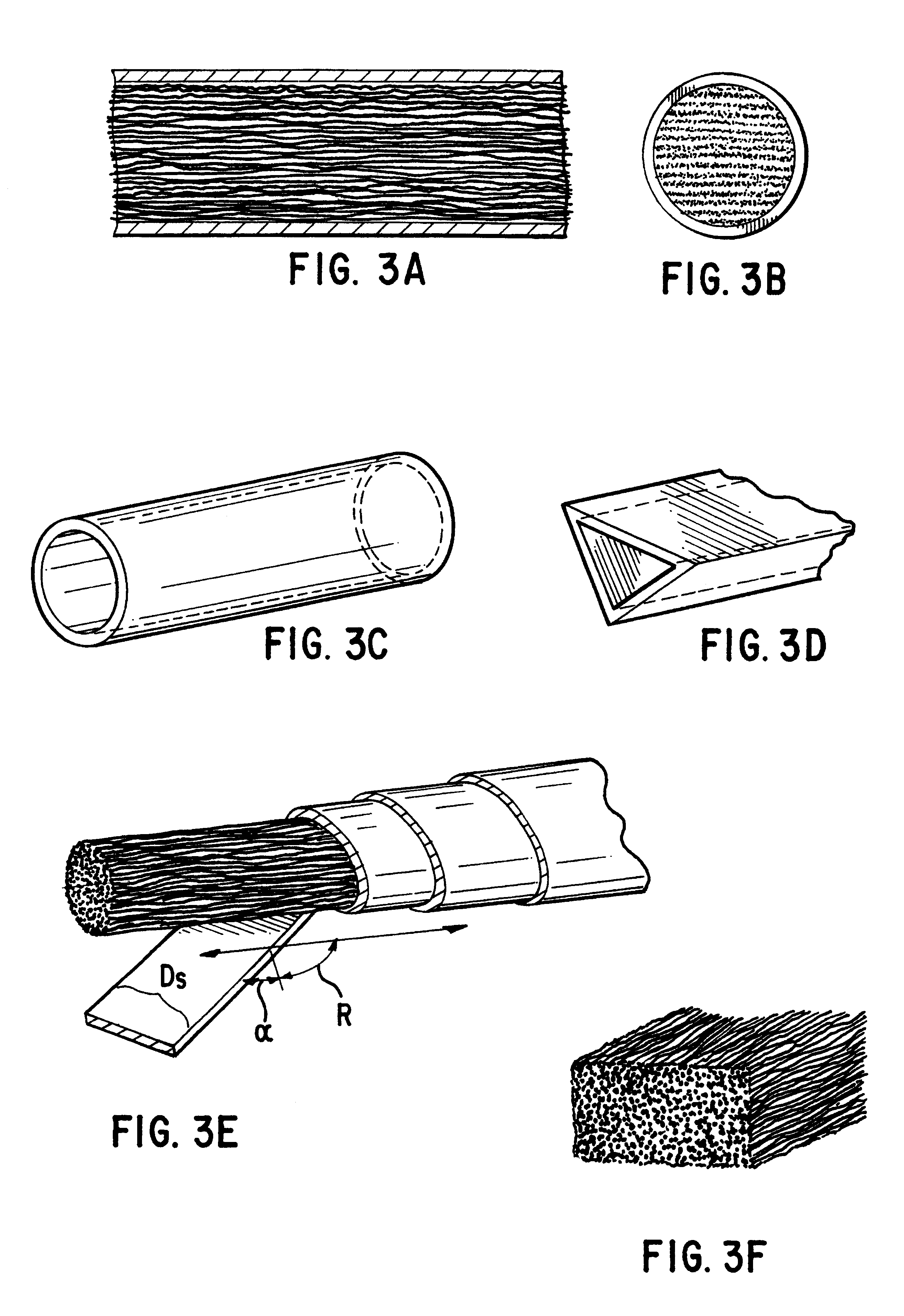
The ideal, therefore, are fibers assembled into the form of rods (brush-stock), typically but not necessarily straight and of constant cross section, which locally leave the fibers within them individually flexible such that the properties at the interface to the conducting surface do not change if run end-on even for long periods of time so as to cause considerable wear.

b. General Characteristics of Brush Stock

The most important feature of fiber brushes is that at any one moment a large number of fibers, el...


PUM

PropertyMeasurementUnit
Fractionaaaaaaaaaa
Fractionaaaaaaaaaa
Fractionaaaaaaaaaa

Abstract

A conductive fiber brush including a brush stock composed of plural conductive fibers or strands of fibers at least some of which may have plural bends along the leg of the fibers or strands. The fibers may have a diameter less than 0.2 mm and are arranged in contacting engagement with each other with the touching points among the fibers or strands maintaining elastic tension between the fibers or strands and thereby maintaining voids between the fibers or strands to produce a packing fraction between 1 and 50% and in extreme cases up to 70% but generally between 10-20% depending on the various factors, including the materials used, the current densities to be conducted, and the sliding speeds under operation. The plural bends are implemented by producing fibers or strands having a regular or irregular spiral, wavy, saw-tooth, triangular, and/or rectangular pattern, or other undulating pattern. Optionally, the voids in brush stock may be partially filled with a strengthening, lubricating, abrasive, and/or polishing material, and may be wrapped in an outer sheath, slid into a casing, or provided with an other covering of all or part of the area of the brush stock, be infiltrated or sprayed at the surface with some material, have an increased packing fraction at the surface and/or have some or all of the touching points between the fibers or strands soldered, welded or otherwise thermally joined. Optionally also, the friction among the fibers may be reduced through light lubrication applied by rinsing the brush or brush stock in a lubricant. In one embodiment, the fiber brush is employed in a brush loading device having a hydrostatically controlled brush holder wherein the force exerted on the brush is controlled by a metallic or other conductive hydrostatic fluid which at the same time conducts the current to the brush.

Description

DESCRIPTION1. Technical FieldThis invention relates to fiber brushes, and in particular, the improvements in the design and manufacture of fiber brushes of the type disclosed in commonly owned U.S. Pat. Nos. 4,358,699 and 4,415,635, the disclosures of which are incorporated by reference herein.2. Background ArtAlthough graphite and metal-graphite brushes have for nearly 100 years dominated the field of electrical brushes, for many applications there now exists a superior form of sliding electrical conduction; high performance fiber brushes wherein typically the fibers are made of metal for which reason they are called metal fiber brushes. Prime candidates for this new technology include sliding electrical systems which require high current densities, high sliding speeds, low electrical noise, high efficiency (low brush losses), compact size, or long brush lifetimes.In particular, low voltage electric motors and generators can be made smaller, more powerful and longer lasting owing t...

Claims


Application Information

Patent Timeline
IPC IPC(8): H01R39/00H01R43/12H01R39/24H01R39/22H02K13/00
CPCH01R39/22H01R39/24H01R43/12Y10T29/49119Y10T428/12465
Inventor KUHLMANN-WILSDORF, DORISMAKEL, DAVID D.GILLIES, GEORGE T.
Owner VIRGINIA UNIV PATENT FOUND OF
Why Eureka
Try Eureka