Air separation process integrated with gas turbine combustion engine driver

a gas turbine and combustion engine technology, applied in the direction of machines/engines, lighting and heating apparatus, furnaces, etc., can solve the problems of inability to import electric power, inability to operate steam systems, and inability to meet the power demand of a large air separation unit using an electrically-driven turbocompressor, etc., to achieve the effect of expanding the product gas stream

Inactive Publication Date: 2001-07-24
AIR PROD & CHEM INC
View PDF32 Cites 116 Cited by
  • Summary
  • Abstract
  • Description
  • Claims
  • Application Information

AI Technical Summary

Benefits of technology

The invention is a method for the separation of a feed gas mixture comprising oxygen and nitrogen, wherein the method comprises: (a) compressing a first gas mixture comprising oxygen to yield a compressed oxidant gas and combusting the compressed oxidant gas and fuel in a combustion engine to generate shaft work and a hot exhaust gas; (b) compressing a second gas mixture comprising oxygen and nitrogen to yield a compressed feed gas mixture, and separat

Problems solved by technology

The power demand for a large air separation unit using an electrically-driven turbocompressor may exceed the capabilities of the available electric power system.
At remote locations, imported electric power may be esse

Method used


Image

  • Air separation process integrated with gas turbine combustion engine driver
  • Air separation process integrated with gas turbine combustion engine driver
  • Air separation process integrated with gas turbine combustion engine driver

Examples


first embodiment

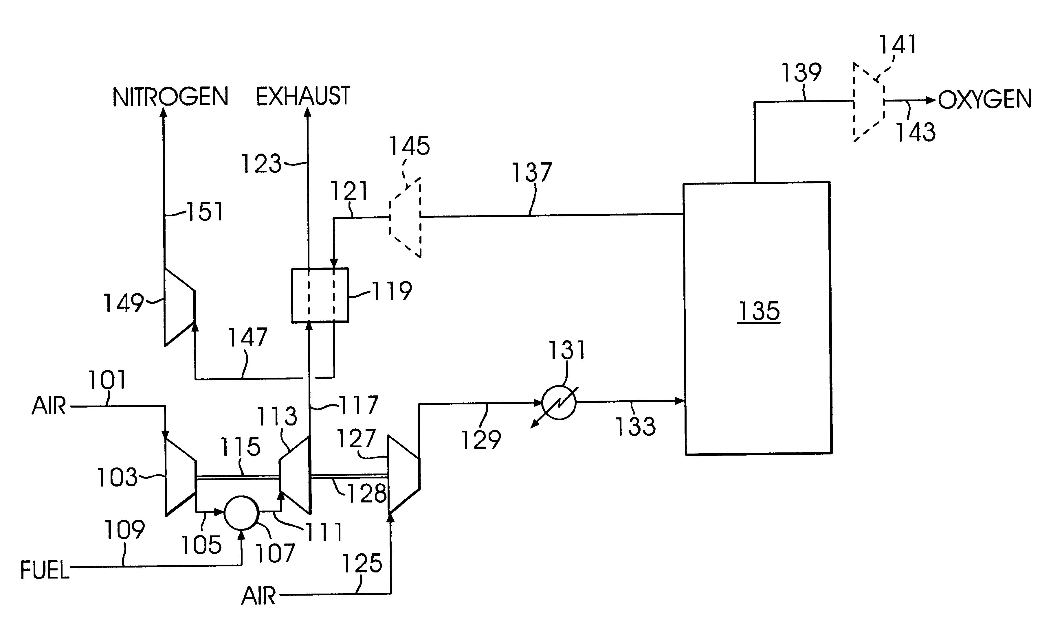
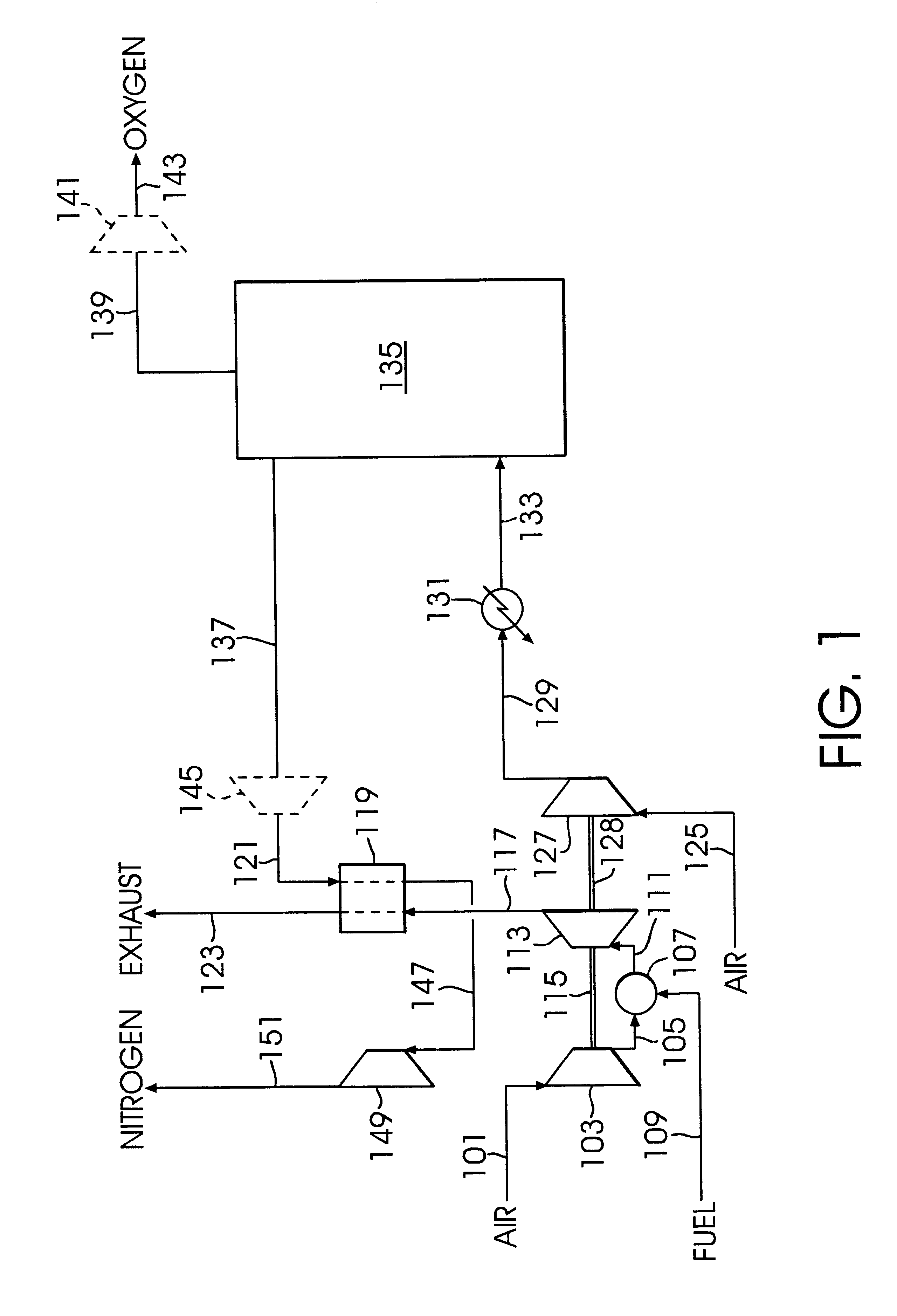
the invention is illustrated in FIG. 1. An oxygen-containing gas feed stream, typically atmospheric air, as stream 101 is compressed in turbocompressor 103 to 48-590 psia and 160-1500.degree. F. Compressed air stream 105 is combusted in combustor 107 with fuel stream 109 to produce hot pressurized combustion gas stream 111. Fuel stream 109 can be any appropriate fuel compatible with the operation of combustor 107.

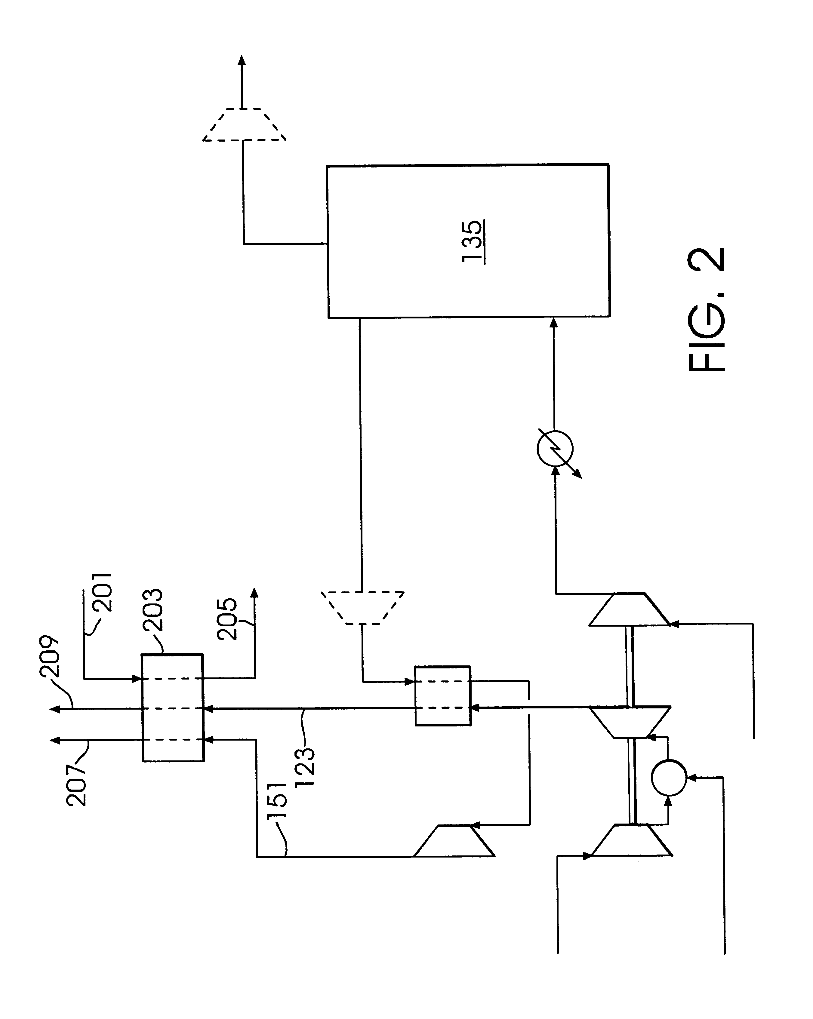
Hot pressurized combustion gas stream 111 is expanded in expansion turbine 113 to produce useful work, and expansion turbine exhaust stream 117 is discharged at near atmospheric pressure and 200 to 1600.degree. F. This expansion step can be defined as work expansion. Work generated by expansion turbine 113 drives turbocompressor 103 by shaft 115, and if desired additional work may be generated to drive other rotating equipment (not shown). Exhaust stream 117 is cooled in heat exchanger 119 by indirect heat exchange with pressurized nitrogen-enriched stream 121 (later define...

example

The process of FIG. 1 is operated at a barometric pressure of 14.7 psia, an ambient temperature of 91.degree. F., and a relative humidity of 60%; cooling water is available at 90.degree. F. The gas turbine combustion engine as shown in FIG. 1 is used to drive air compressor 127 to supply 686 lb / sec of air at a pressure of 127 psia to air separation unit 135. The air separation unit utilizes a cryogenic distillation process to separate the air into nitrogen-enriched stream 137 at 534 lb / sec and 30.1 psia and oxygen-enriched stream 139 at 152 lb / sec and 31.6 psia with an oxygen purity of 95 vol %. Nitrogen-enriched stream 137 is heated to 950.degree. F. in heat exchanger 119 against exhaust stream 117 and heated nitrogen-enriched stream 147 is work expanded in expansion turbine 149 to yield expanded nitrogen-enriched stream 151 at atmospheric pressure. Expansion turbine 149 generates 28,705 kW of power. Oxygen-enriched stream 139 is compressed in compressor 141 to yield compressed oxy...


PUM

PropertyMeasurementUnit
Pressureaaaaaaaaaa
Compositionaaaaaaaaaa
Flow rateaaaaaaaaaa

Abstract

A method for the separation of a feed gas mixture comprising oxygen and nitrogen in which an oxidant gas and fuel are combusted in a combustion engine to generate shaft work and a hot exhaust gas, the feed gas mixture comprising oxygen and nitrogen is compressed, and the resulting compressed feed gas mixture is separated into two or more product gas streams with differing compositions. The shaft work of the combustion engine is utilized to provide at least a portion of the work required for compressing the feed gas mixture, one of the product gas streams by is heated by indirect heat exchange with the hot exhaust gas from the combustion engine, and the resulting heated product gas is work expanded to generate shaft work and yield an expanded product gas stream. The combustion engine may be a gas turbine combustion engine.

Description

CROSS-REFERENCE TO RELATED APPLICATIONSNot applicable.STATEMENT REGARDING FEDERALLY SPONSORED RESEARCH OR DEVELOPMENTNot applicable.BACKGROUND OF THE INVENTIONNew chemical and refining processes, and the economies of scale of such processes, will require increasing quantities of gaseous oxygen at a single location. Requirements for 15,000 tons per day, or more, of gaseous oxygen delivered at pressures of 1,250 psia or higher are anticipated for such processes. Some of these facilities requiring large quantities of gaseous oxygen will be constructed and operated at geographically remote locations.A large air separation unit to produce gaseous oxygen requires a compressed air feed stream which is typically provided from atmospheric air by an intercooled turbocompressor driven by an electric motor. Electric motor driven turbocompressors also are utilized to compress the gaseous oxygen and other air separation process by-products.As the required capacities for air separation units incre...

Claims


Application Information

Patent Timeline
IPC IPC(8): F02C6/06F02C6/00F25J3/04
CPCF02C6/06F25J3/0403F25J3/04036F25J3/04115F25J3/04127F25J3/04139F25J3/04181F25J3/04581F25J3/04593F25J3/04612F25J3/04618F25J3/04018F25J2240/82F25J2200/20F25J2205/70
Inventor DILLON, IV, JOHN LLOYDGRIFFITHS, JOHN LOUIS
Owner AIR PROD & CHEM INC
Why Eureka
Try Eureka