Distributed network synchronization system

a distributed network and synchronization technology, applied in the field of telecommunications, can solve the problems of increasing the relative delay in the network, exacerbate the problem, and the ring latency is becoming the largest contributor to the reduction of performance in the distributed network system

Inactive Publication Date: 2001-08-21
EXCEL SWITCHING
View PDF36 Cites 78 Cited by
  • Summary
  • Abstract
  • Description
  • Claims
  • Application Information

AI Technical Summary

Benefits of technology

In brief summary, the present invention provides a distributed synchronization system for use in connection with a distributed, asynchronous, telecommunications network system that continually monitors and controls the flow of data through an implementing network node so as to prevent dataflow errors due to phase and frequency differences in source and destination nodal clocks.
A word resynchronization subsystem manages the flow of data through the data FIFO of each non-master node, receiving and storing the data at the source node's clock rate and re-transmitting the data at its own clock rate. Thus, the word resynchronization subsystem controls the operation of the synchronization data FIFO to effectively absorb any phase difference between the clocks of a source node and a destination node implementing the invention. A write controller, operating at the source node clock rate, and a read controller, operating at the destination node clock rate, asynchronously manage the passage of data through the data FIFO to maintain the level of data in the FIFO within an optimal range. During the receipt of a predetermined portion of a frame transmission which contains no valid data, the FIFO read and write controllers may temporarily suspend read and / or write operations from / to the FIFO to maintain the data level within the optimal range for efficient data transfer across the network.
Advantageously, the word resynchronization subsystem of the present invention prevents data FIFO overflow and underflow conditions from arising, thereby ensuring substantially error-free transmission through the implementing network node. A significant feature of the word resynchronization subsystem is its anticipatory nature, enabling it to compensate for phase differences between clock signals before data is lost. Another feature provided by the invention is the ability to momentarily control either or both the reading and writing of data from and to the FIFO to recover from clock deviations without loss of data and without causing substantial delays in the network.
The frame synchronization subsystem, on the other hand, buffers only the payload and frame synchronization fields of the frame packet, which are held until the beginning of a frame cycle, as determined by the occurrence of a local frame synchronization pulse. In response to that pulse, the frame synchronization subsystem transmits the frame synchronization and payload fields, onto which this subsystem appends a new, locally-determined dead zone to create a frame packet that is precisely one frame in length. This aspect of the present invention advantageously ensures that every non-master node receives a frame packet at predetermined intervals of time. In turn, such predictable and periodic receipt of frame packets enables the receiving nodes to precisely determine the boundaries between synchronous data samples contained within the frame packets. Furthermore, the frame synchronization subsystem automatically adjusts the amount of data buffered in the master node, dynamically self-adjusting to changes in the ring latency which may be caused, for example, by the addition (or deletion) of nodes to the network.

Problems solved by technology

There are two major contributors to ring latency: the propagation delay required for a frame packet to cycle once around the ring; and the delay required to retransmit a frame packet at each node on the ring.
However, the increased capability of the fiber optic network to send more bits per unit time, as well as the increased capability of nodes to perform more instructions per unit time, results in an increase in the relative delay in the network.
As a result, ring latency is becoming the largest contributor to the reduction of performance in distributed network systems.
This problem is exacerbated in widely distributed network systems since propagation delay increases with distance.
In addition, as the node-to-node distance increases in a geographically distributed network system, the propagation delay, and thus ring latency, becomes unpredictable.
The unpredictability of distributed network systems is particularly problematic when the network is required to carry synchronous data such as pulse coded modulation (PCM) data commonly used in telecommunications networks.
The unpredictable arrival of frame packets prevents the receiving node from accurately identifying the divisions between PCM samples, thereby inhibiting the transfer of synchronous data through the asynchronous network.
However, despite being designed to operate at the same frequency, timing variations inevitably exist among network components.
Underflow and overflow conditions, generally referred to as slip, typically result in errors within the network.
For example, in a voice circuit, slip may appear as popping or clicking sounds, whereas in data transmissions, slip is manifested by the loss of data.
Very large buffers can reduce the probability of such errors, but they increase the delay through the network.
This continual adjustment around the desired frequency causes jitter.
Eventually, this accumulated jitter may become too large, thereby resulting in data loss.
Another drawback to conventional clock recovery systems is that they are based upon the assumption that identical network reference clocks are provided to the source and destination nodes.
This is often not the case in geographically-distributed telecommunications systems.
Moreover, if a network element such as a digital cross connect fails, certain network nodes may lose their reference clock.
These nodes must then utilize their internal clocks, resulting in an increased loss of data due to the difference in phase and frequency between such nodes' internal clocks and the reference clocks.

Method used


Image

  • Distributed network synchronization system
  • Distributed network synchronization system
  • Distributed network synchronization system

Examples


Embodiment Construction

A. System Environment

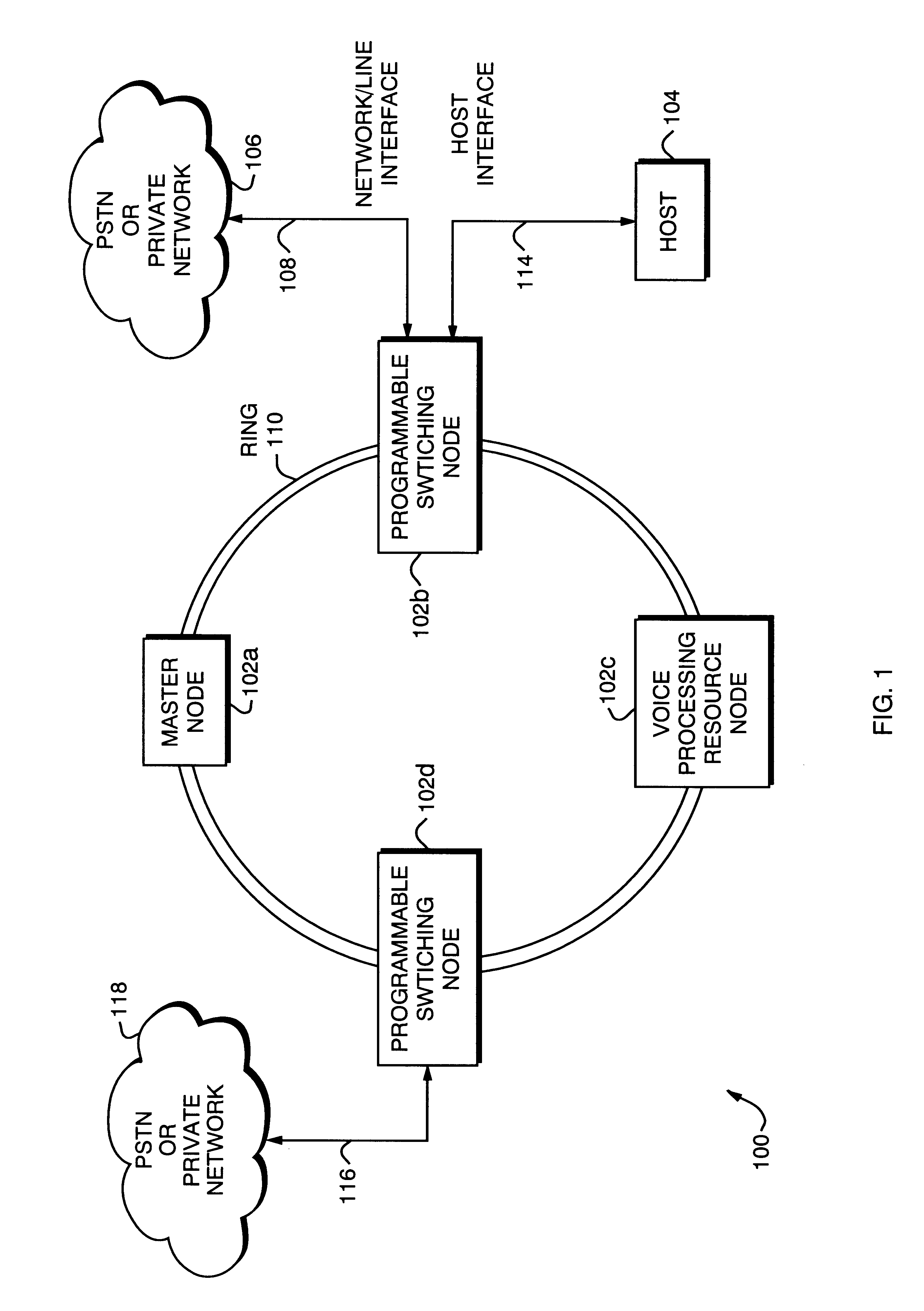
FIG. 1 shows a large capacity, expandable, fully programmable telecommunications switching network system 100. The network system 100 includes a series of programmable nodes 102 interconnected by a ring-architecture, inter-nodal network 110. The programmable nodes include a master node 102a, programmable switching nodes 102b, 102d, and a voice processing resources node 102c. A host link 114 connects node 102b in communicating relationship with a host computer 104. Nodes 102a, 102c and 102d may be controlled by host computer 104, whether by additional host links to such nodes, by passing control information over inter-nodal network 110 or by separate host devices. Although only a single host computer 104 and host link 114 are shown for purposes of improved clarity, use of a local area network (LAN) to provide host / node communications permits multiple hosts to control the system 100 (or parts thereof) by configuring each host as a "client" and each node as a "serv...


PUM


Abstract

A distributed synchronization system for use in each node of a distributed asynchronous telecommunications network system that continually monitors and controls the flow of data through an implementing node to prevent dataflow errors due to phase and frequency differences in source and destination nodal clocks, and to control inter-nodal network latency so as to support the transmission of synchronous data. A synchronization data FIFO buffers predetermined fields or portions of fields of a unique frame packet received from a source node before retransmission to a destination node on the network. The frame packet includes a frame synchronization field indicating the beginning of a new frame packet; a payload field containing valid data; and a dead zone field providing bandwidth during which the present invention performs synchronization functions. A frame synchronization subsystem, implemented in a designated master node, guarantees that a frame is released at the beginning of an independently-determined frame regardless of network latency. A word resynchronization subsystem manages the flow of data through the data FIFO of each non-master node, receiving and storing data at the source node's clock rate and transmitting the data according to its own clock, thereby guaranteeing the efficient receipt and transmission of data between asynchronously-communicating nodes.

Description

CROSS-REFERENCES TO RELATED APPLICATIONS AND PATENTSThe following commonly-owned patents and applications are related to the present invention and are incorporated by reference by this and other references:U.S. Pat. No. 5,544,163, entitled "Expandable Telecommunications System," naming as inventor Robert P. Madonna;U.S. Pat. No. 5,426,694, entitled "Telecommunications Switch Having Programmable Network Protocols and Communications Services," naming as inventor Mark P. Hebert;U.S. patent application Ser. No. 08 / 566,414, entitled "Telecommunications Switch Having A Universal Applications Program Interface," naming as inventor Mark P. Hebert, filed on Nov. 30, 1995; andU.S. Pat. No. 5,349,579, entitled "Telecommunications Switch With Programmable Communications Services," naming as inventors Robert P. Madonna and Kevin C. Kicklighter.BACKGROUND OF THE INVENTION1. Field of the InventionThis present invention relates generally to the field of telecommunications and, more specifically, to...

Claims


Application Information

Patent Timeline
Patent Type & Authority Patents(United States)
IPC IPC(8): H04J3/06H04L12/42H04L7/00
CPCH04L12/422H04J3/0626
Inventor ESCHHOLZ, SIEGMAR K.
Owner EXCEL SWITCHING
Why Eureka
Try Eureka