

Fuel hose
a technology of fuel hoses and hoses, which is applied in the direction of flexible pipes, heat exhanger conduits, mechanical devices, etc., can solve the problems of not being able to meet the permeation regulation of gasoline, the melting point of ozone resistance of hoses, and the difficulty of reducing the film thickness of resins, etc., to achieve excellent ozone resistance, reduce the melting point, and reduce the temperature in film formation
- Summary
- Abstract
- Description
- Claims
- Application Information
AI Technical Summary
Benefits of technology
Problems solved by technology
Method used
Image

Examples
first example
(Manufacture of Fuel Hose)
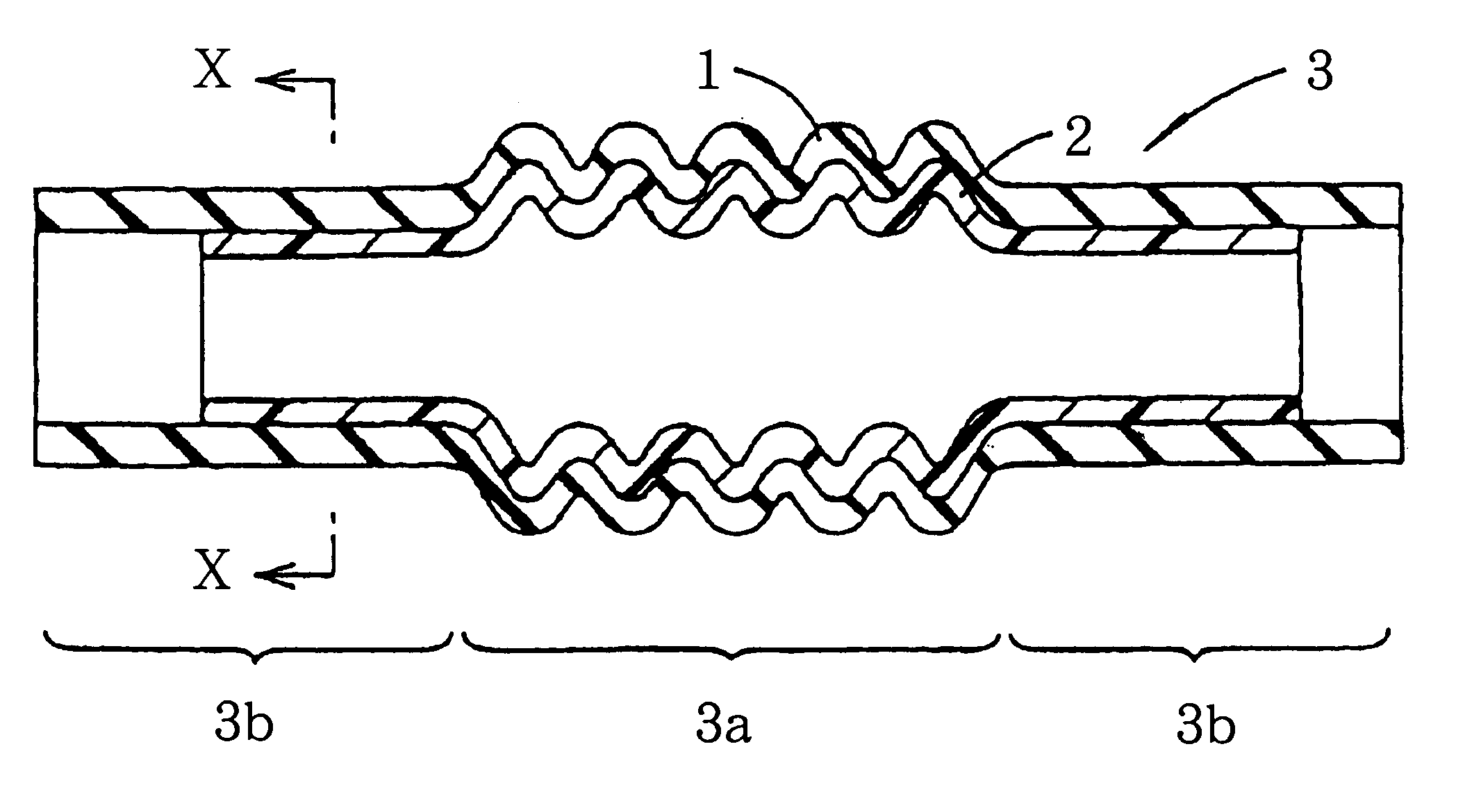
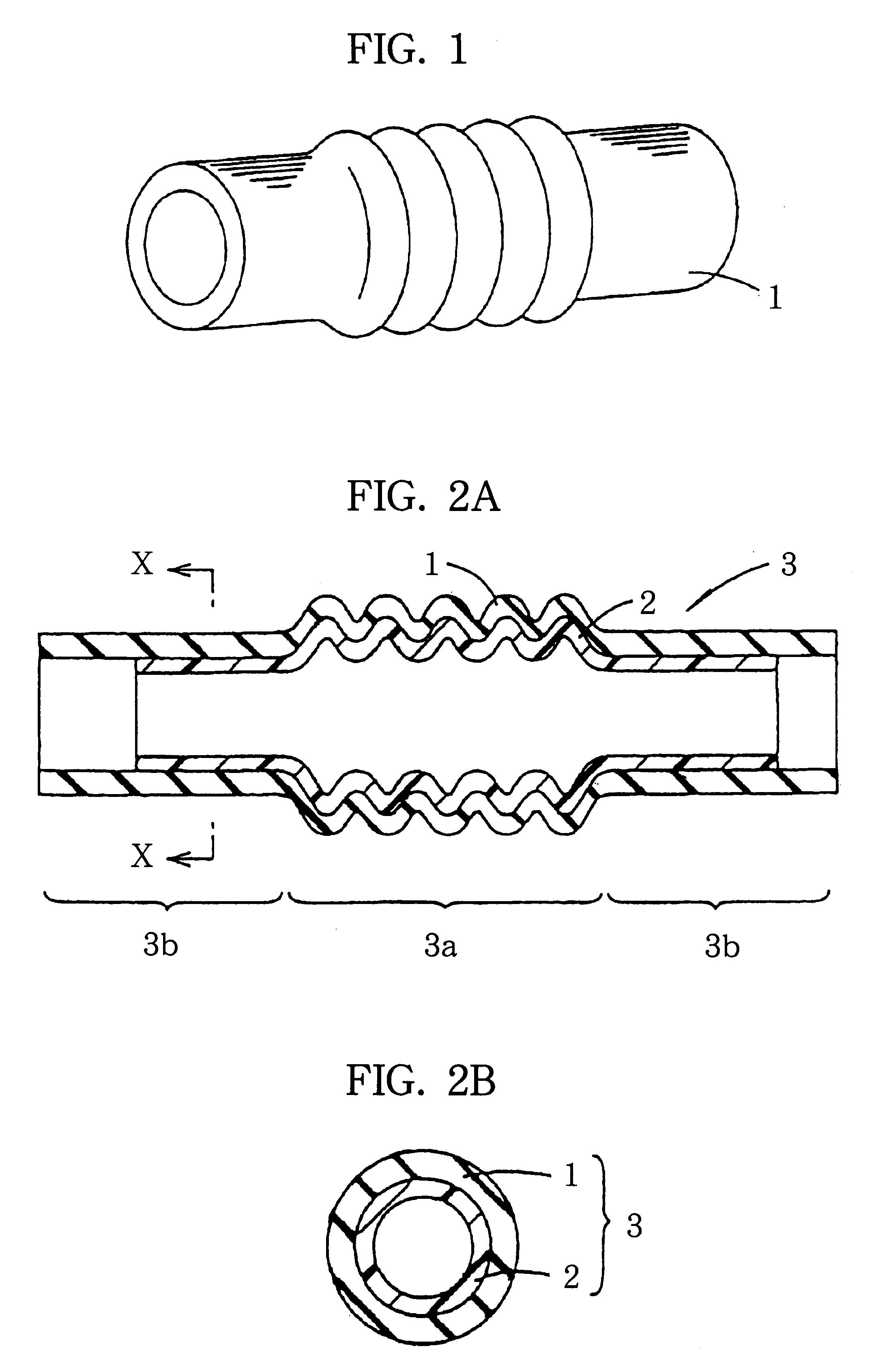
In the same manner as explained for FIG. 1 to FIG. 3, fuel hoses of Examples 1 to 3 and Comparative Examples 1 to 4 in Table 1 were manufactured. Each has an identical tubular rubber body and a thin film resin layer of a different material.
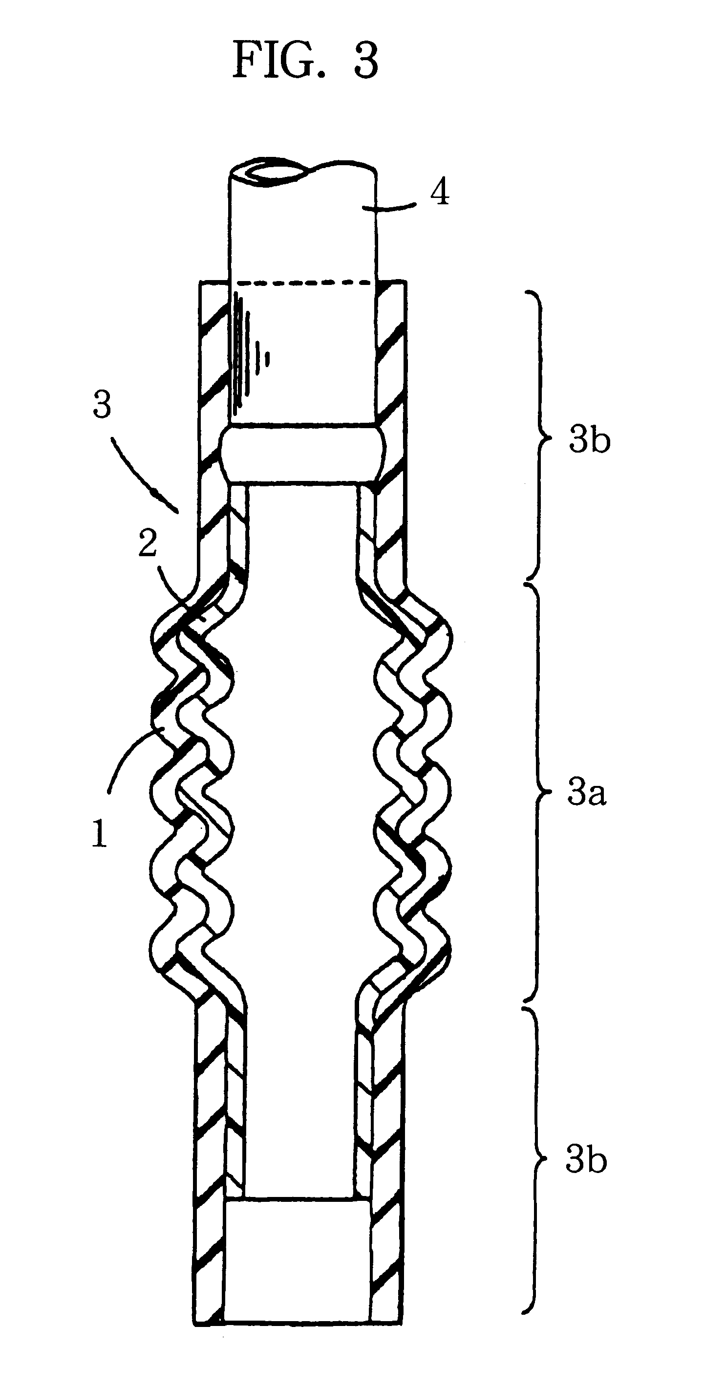
Specifically, by using unvulcanized rubber compositions in which predetermined vulcanizers, adhesion agents or necessary additives such as carbon black were added to unvulcanized NBR / PVC, tubular rubber bodies were vulcanized / molded by injection molding under the conditions at 160.degree. C. for 5 minutes. The tubular rubber body had a convolutional structure at a middle portion, and had a wall thickness of 4 mm, an inner diameter of 35 mm at a straight tube portion and a length of 200 mm.
Then, the resin powder of the type shown in each of the examples in Table 1 was deposited on a predetermined portion of the inner circumferential surface of the tubular rubber body by electrostatic coating utilizing corona discharging mi...
second example
In the same manner as in the first example, fuel hoses of Examples 4 to 10 in Table 2 each having the tubular rubber body formed of a different material and the identical thin film resin layer were manufactured. Specifically, the rubber materials shown in Table 2 were used for the tubular rubber body, and each of the thin film resin layers was the same as in Example 1 above. Then, the evaluations of the films formed, the flexibility and the fuel impermeability were conducted for the fuel hose in each of the examples in the same manner as in the first example. The results are shown in Table 2 in the same manner as those in Table 1.
third example
(Manufacture of Fuel Hose)
Fuel hoses in Example 11, and Comparative Examples 5 and 6 in Table 3 each having an identical tubular rubber body and a different thin film resin layer were manufactured in the same manner as explained for FIG. 1 to FIG. 3. In the third example, previous blending of the plasticizer with the material of the thin film resin layer for lowering the melting point of the resin was not conducted.
Specifically, by using unvulcanized rubber compositions in which predetermined vulcanizers, adhesion agents or necessary additives such as carbon black were added to unvulcanized NBR / PVC tubular rubber bodies were vulcanized / molded by injection molding at 160.degree. C. for 5 minutes. The tubular rubber body had a convolutional structure at a middle portion, and had a wall thickness of 4 mm, an inner diameter of 35 mm at a straight tube portion and a length of 200 mm.
Then, the resin powder shown in each of the examples in Table 3 was deposited on a predetermined portion o...
PUM
 Abstract
Description
Claims
Application Information