Process for oligomer production and saturation
a technology of oligomer and process, applied in the direction of organic chemistry, chemical apparatus and processes, hydrocarbon preparation catalysts, etc., can solve the problems of not being economically advantageous, not being able to meet the needs of oligomerization, and being susceptible to catalyst fouling,
- Summary
- Abstract
- Description
- Claims
- Application Information
AI Technical Summary
Benefits of technology
Problems solved by technology
Method used
Image
Examples
example 2
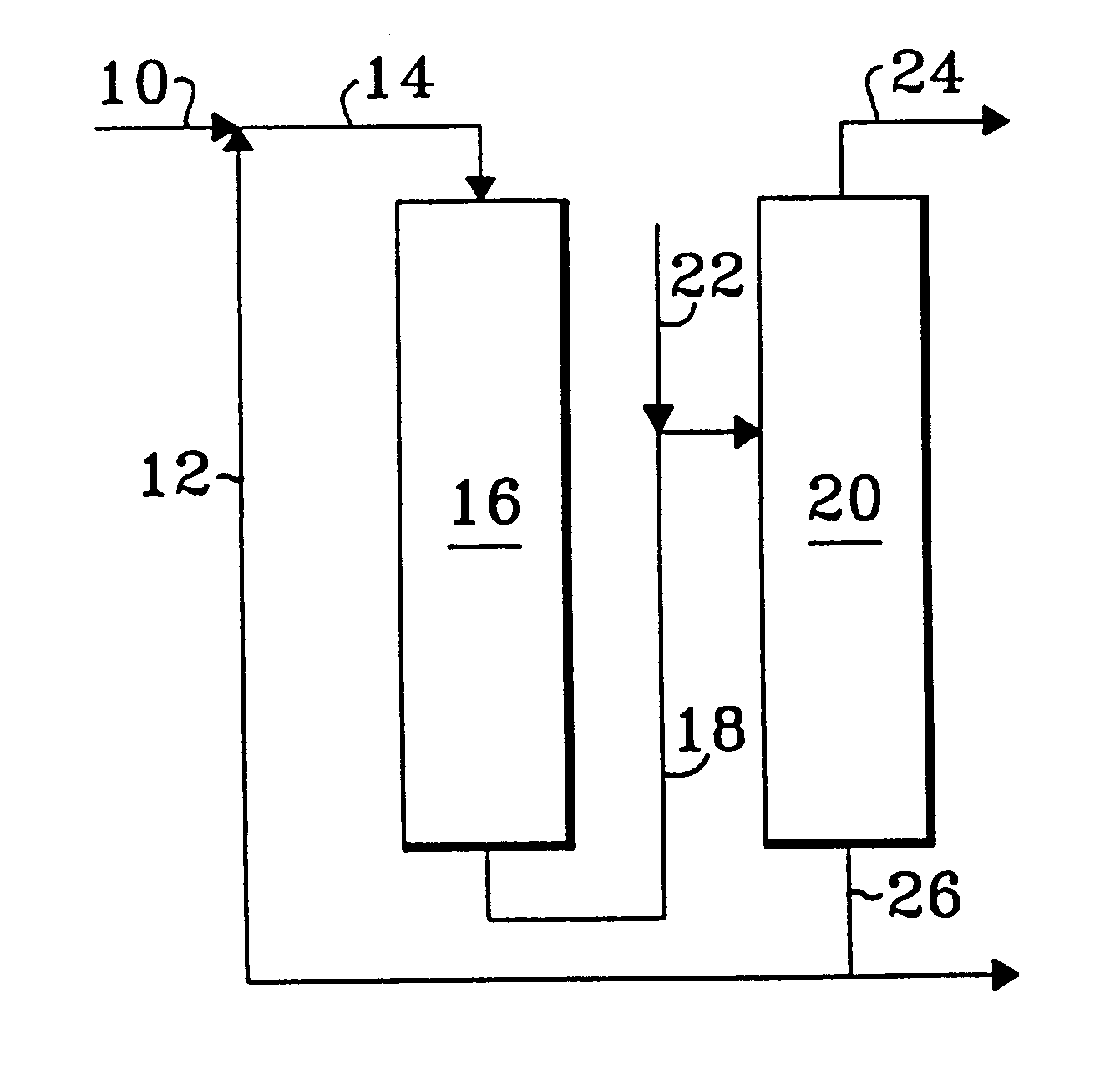
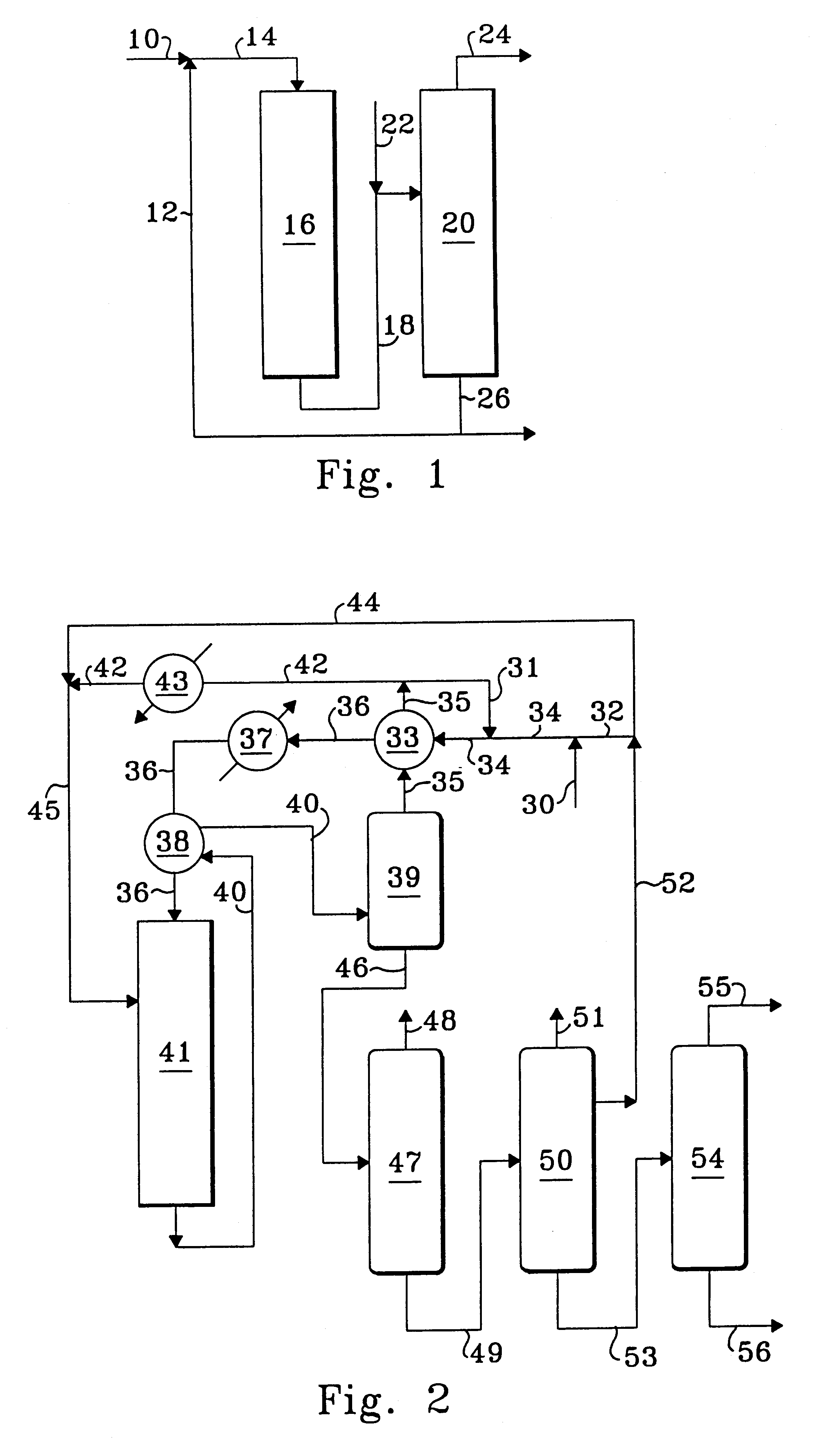
In order to demonstrate the advantages of a heavy recycle, an additional 25 wt-% of normal C.sub.8 paraffins was added to the feed of Example 1 and run at the operating conditions and with the same catalyst as Example 1. The oligomerization zone reached a maximum temperature of 392.degree. F. A sample of the effluent from the reaction zone was again distilled and analyzed and found to contain a significantly higher percentage of C.sub.8 olefins. The results of the analysis are again shown in Table 1.
Comparison of Examples 1 and 2 demonstrates that at approximately equal C.sub.4 olefin conversions the addition of the C.sub.8 paraffins shifted the selectivity of the reactor effluent significantly toward the production of the highly desired C.sub.8 isomer and surprisingly away from the production of both higher and lower carbon number isomers.
As this example demonstrates, the recycle stream of this invention provides a significant improvement in the selectivity of the oligomerization t...
example 3
A feedstream having a composition of 8.4 wt-% normal butene, 21.9 wt-% isobutene and 69.7 wt-% isobutane was contacted with about 50 cc of an SPA catalyst of the type used in Examples 1 and 2. The reactor vessel and catalyst loading technique was also of the same type used in Examples 1 and 2. Feed entered the reactor at a temperature of 376.degree. F. and a pressure of 500 psig and passed through the reactor at a liquid hourly space velocity of 2. The oligomerization reaction produced a maximum reactor temperature of about 403.degree. F. A sample of the reactor effluent was recovered hydrogenated, distilled and analyzed to determine the conversion of C.sub.4 olefins, the carbon number selectivities of the products and the research and motor octane number. The results of the analyses are shown in Table 2.
examples 4-6
In order to demonstrate the advantages of a heavier components than C.sub.8 and lower operating temperatures an additional 25 wt-% of normal C.sub.12 paraffins were added to the feed of Example 3 and run at a range of reduced operating temperatures and space velocities with the same catalyst as Example 3. Conversions, selectivity and research and motor octane numbers after distillation and hydrogenation of effluents from the three runs with the added C.sub.12 components to the feed are shown in Table 2 as Examples 4-6.
All three of the runs operated with reduced temperatures relative to Example 3 and show significant improvement to the C.sub.8 selectivity by the addition of the normal C.sub.12 paraffins. Examples 4 and 5 both demonstrate a much higher selectivity to C.sub.8 isomers than Example 3 at an only slightly reduced conversion. The improved selectivity resulted in a much higher octane number than that obtained without the C.sub.12 components in Example 3. Example 6 demonstrat...
PUM
| Property | Measurement | Unit |
|---|---|---|
| Fraction | aaaaa | aaaaa |
| Fraction | aaaaa | aaaaa |
| Fraction | aaaaa | aaaaa |
Abstract
Description
Claims
Application Information
 - R&D
- Intellectual Property
- Life Sciences
- Materials
- Tech Scout
- Unparalleled Data Quality
- Higher Quality Content
- 60% Fewer Hallucinations
Browse by: Latest US Patents, China's latest patents, Technical Efficacy Thesaurus, Application Domain, Technology Topic, Popular Technical Reports.
© 2025 PatSnap. All rights reserved.Legal|Privacy policy|Modern Slavery Act Transparency Statement|Sitemap|About US| Contact US: help@patsnap.com


