
Method of reworkably removing a fluorinated polymer encapsulant

a fluorinated polymer and encapsulant technology, applied in semiconductor/solid-state device testing/measurement, manufacturing tools, instruments, etc., can solve the problems of difficult application, high cure temperature, and low temperature and humidity resistance of application and removal

Inactive Publication Date: 2001-10-23
TERAVICTA TECH
View PDF21 Cites 30 Cited by
  • Summary
  • Abstract
  • Description
  • Claims
  • Application Information

AI Technical Summary

Benefits of technology

The present invention provides an improved fluorinated polymer encapsulant for protectively coating electronic devices in an electronic device module. Also provided is a method for applying and reworkably removing the same to and from the electronic device module. In one embodiment, a coating of a fluorinated polymer solution is applied to at least a portion of an electronic device module. The module is then baked to operably fix to it the fluorinated polymer coating.

Problems solved by technology

For example, acrylics are generally easy to apply and remove but typically exhibit low temperature and humidity resistance.
Conversely, polyimides, generally have high temperature and humidity resistance but are difficult to apply, require a high cure temperature, and have short pot life.
Unfortunately, however, RTV is reactive and cannot be directly applied without extensive board preparation.
Epoxy coatings may be applied as glob-top encapsulants, but because epoxy has a significantly different thermal expansion coefficient than most printed circuit board materials, the curing process and environmental thermal cycling can result in unacceptable mechanical stress and failure at the component or board level.
In addition, epoxies are not generally acceptably reovable for rework.
Polyurethane has also been used for such coatings, but is unstable under high temperature and humidity.
Significantly, most of these currently employed coatings are difficult to remove, making repair problematic and, in some cases, practically impossible.

Method used


Image

  • Method of reworkably removing a fluorinated polymer encapsulant
  • Method of reworkably removing a fluorinated polymer encapsulant
  • Method of reworkably removing a fluorinated polymer encapsulant

Examples


first embodiment

a. First Embodiment

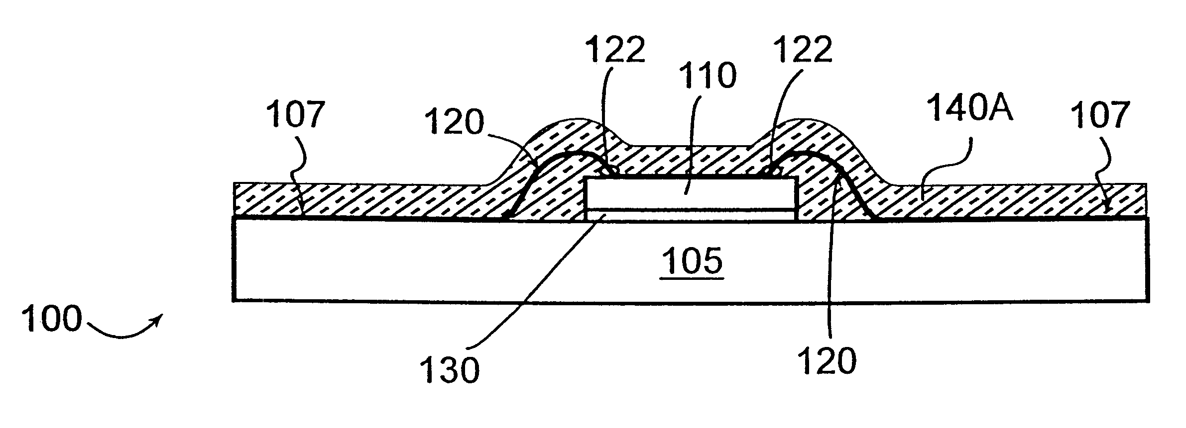
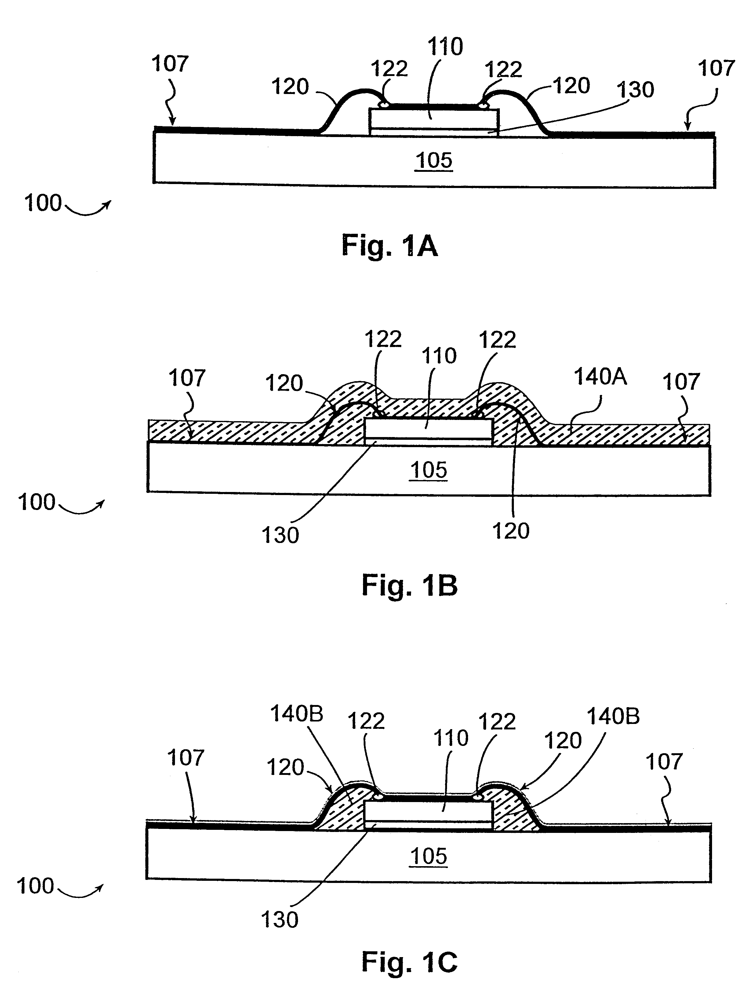
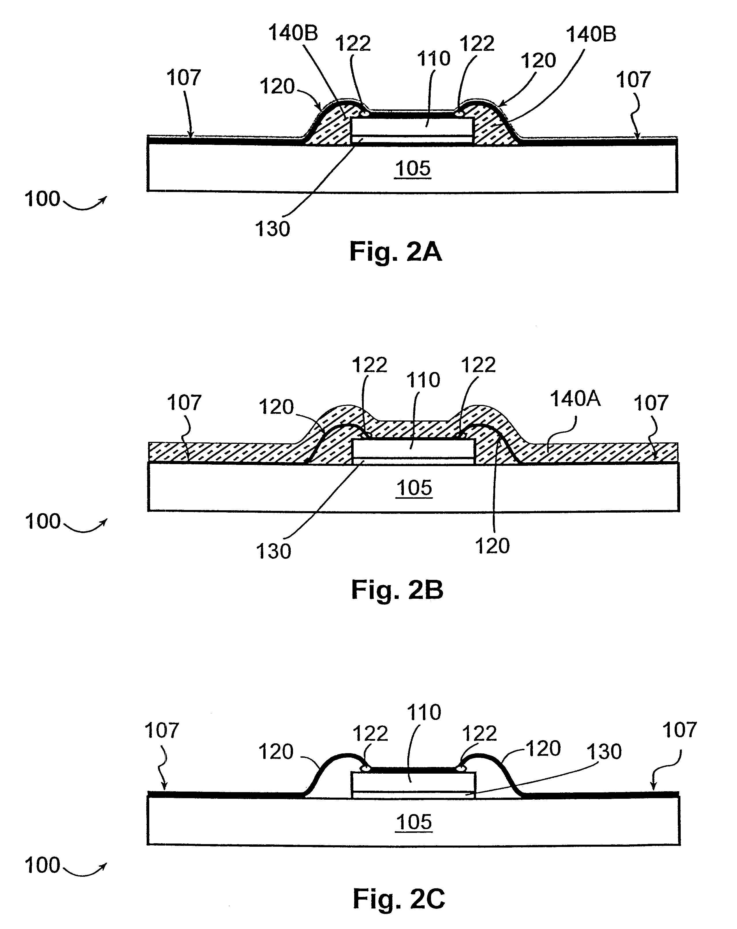
FIGS. 1A, 1B, and 1C schematically depict various stages of encapsulating one embodiment of an electronic device module 100 with the present invention. Conversely, FIGS. 2A, 2B, and 2C show various stages of removing the coating from the module in order to rework it.

Electronic device module 100 includes electronic devices such as bare integrated circuit chips 110 operably mounted to a printed circuit board ("PCB") 105 through adhesive 130. The electronic devices 110 are electrically connected to the PCB 105 through conductors 120. In the depicted embodiment, conductors 120 are wire bonded at one end 122 to the electronic device 110 and at the other end to the PCB metallization 107. FIG. 1A shows electronic device module 100 prior to being coated with a fluorinated polymer of the present invention. FIG. 1B shows the module 100 after fluorinated polymer solution 140A has been applied. At this point, the coating is "wet" and not yet fixed to the module. Finally, FIG....


PUM

PropertyMeasurementUnit
temperatureaaaaaaaaaa

Abstract

The present invention provides an improved fluorinated polymer encapsulant for protectively coating electronic devices in an electronic device module. Also provided is a method for applying and reworkably removing the same to and from the electronic device module. In one embodiment, a coating of a fluorinated polymer solution is applied to at least a portion of an electronic device module. The module is then baked to operably fix to it the fluorinated polymer coating.

Description

1. TECHNICAL FIELDThe present invention relates to protective coatings for electronic devices and, in particular, to a protective fluorinated polymer coating.2. BACKGROUNDProtective device encapsulants, e.g., conformal coatings were originally developed to protect sensitive electronic assemblies from the harsh environments experienced in military, aerospace and marine domains. However, as the level of integration has increased in the electronic industry, e.g., with SMT and finer lead pitches associated with VLSI circuitry, the use of and need for adequate protective coatings has spread into a variety of commercial (as well as military) applications.The continuing miniaturization of electronic systems has resulted in the integration of direct-chip-attach (or DCA) and chip-scale-package (or CSP) technologies. These technologies allow for the miniaturization of electronic systems by means of eliminating large chip packages. However, improved protective coatings and associated applicati...

Claims


Application Information

Patent Timeline
Patent Type & Authority Patents(United States)
IPC IPC(8): H01L21/02H01L21/56H01L23/28H01L23/31H01L23/29H05K3/28
CPCH01L21/56H01L23/293H01L23/3121H01L21/563Y10T29/49721H01L2224/16225H01L2224/32225H01L2224/48091H01L2224/48227H01L2224/48465H01L2224/73203H01L2224/73204H01L2224/73265H01L2924/01039H01L2924/1815H01L2924/19041H05K3/288H01L2224/8592H01L24/48H01L2924/00014H01L2924/00H01L2224/05599H01L2924/181H01L2224/85399H01L2924/14H01L2924/00012H01L2224/45015H01L2924/207H01L2224/45099
Inventor LUNCEFORD, BRENT D.
Owner TERAVICTA TECH
Learn More