Electrolyzer

a technology of electrolysis and electrolysis components, which is applied in the direction of electrolysis components, specific water treatment objectives, water/sewage treatment by oxidation, etc., can solve the problems of poor energy efficiency of production, high cost of generating equipment, and potential danger of transportation

Inactive Publication Date: 2001-10-30
LYNNTECH
View PDF8 Cites 60 Cited by
  • Summary
  • Abstract
  • Description
  • Claims
  • Application Information

AI Technical Summary

Problems solved by technology

In addition, since ozone is explosive when concentrated as either a gas or liquid, or when dissolved into solvents or absorbed into cells, its transportation is potentially hazardous.
However, the cost of generating equipment, and poor energy efficiency of production has deterred its use in many applications and in many locations.
Such O.sub.3 concentrations, while quite poor, in an absolute sense, are still sufficiently high to furnish usable quantities of O.sub.3 for the indicated commercial purposes.
Another disadvantage of the corona process is the production of harmful NO.sub.x otherwise known as nitrogen oxides.
Other than the aforementioned electric discharge process, there is no other commercially exploited process for producing large quantities of O.sub.3.
Thus, the electrolytic process appears to be at about a six-fold disadvantage.
Heretofore, the necessary high yields have not been realized in any forseeably practical electrolytic system.
However, such yields could only be achieved utilizing very low electrolyte temperatures, e.g., in the range from about -30.degree.C. to about -65.degree..
Maintaining the necessary low temperatures, obviously requires costly refrigeration equipment as well as the attendant additional energy cost of operation.
Because ozone has such a strong oxidation potential, it has a very short half-life.
For example, ozone which has been solubilized in waste water may decompose in a matter of 20 minutes.
Because so many of the present applications for ozone deal with the oxidation of contaminants in water streams, air streams and soil, it is typically impractical to bring the contaminant to a centralized ozone processing plant.
Unfortunately, there has been very little attention given to the development of self-contained and self-controlled support systems and utilities for ozone producing electrochemical cells.

Method used


Image

  • Electrolyzer
  • Electrolyzer
  • Electrolyzer

Examples


Embodiment Construction

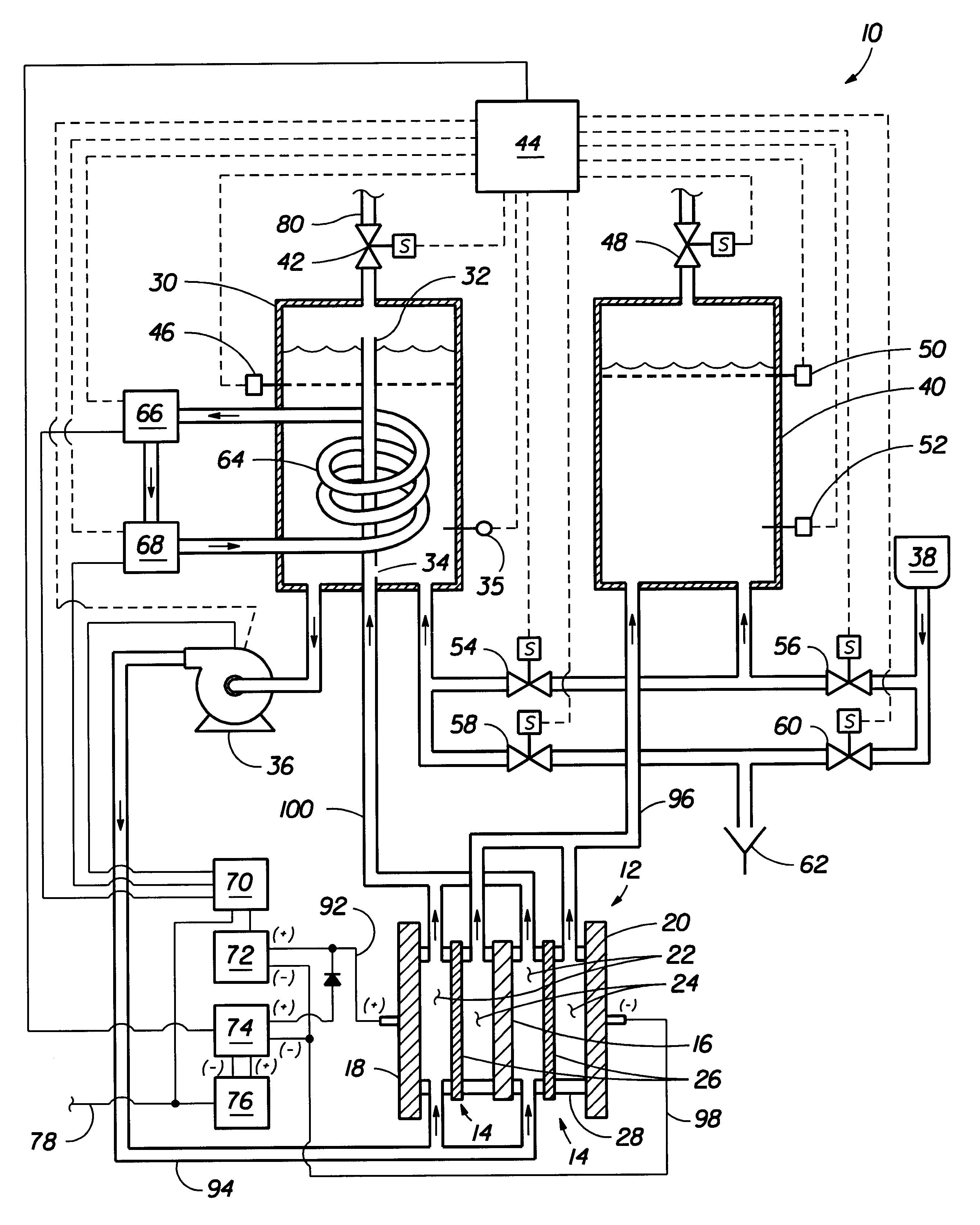
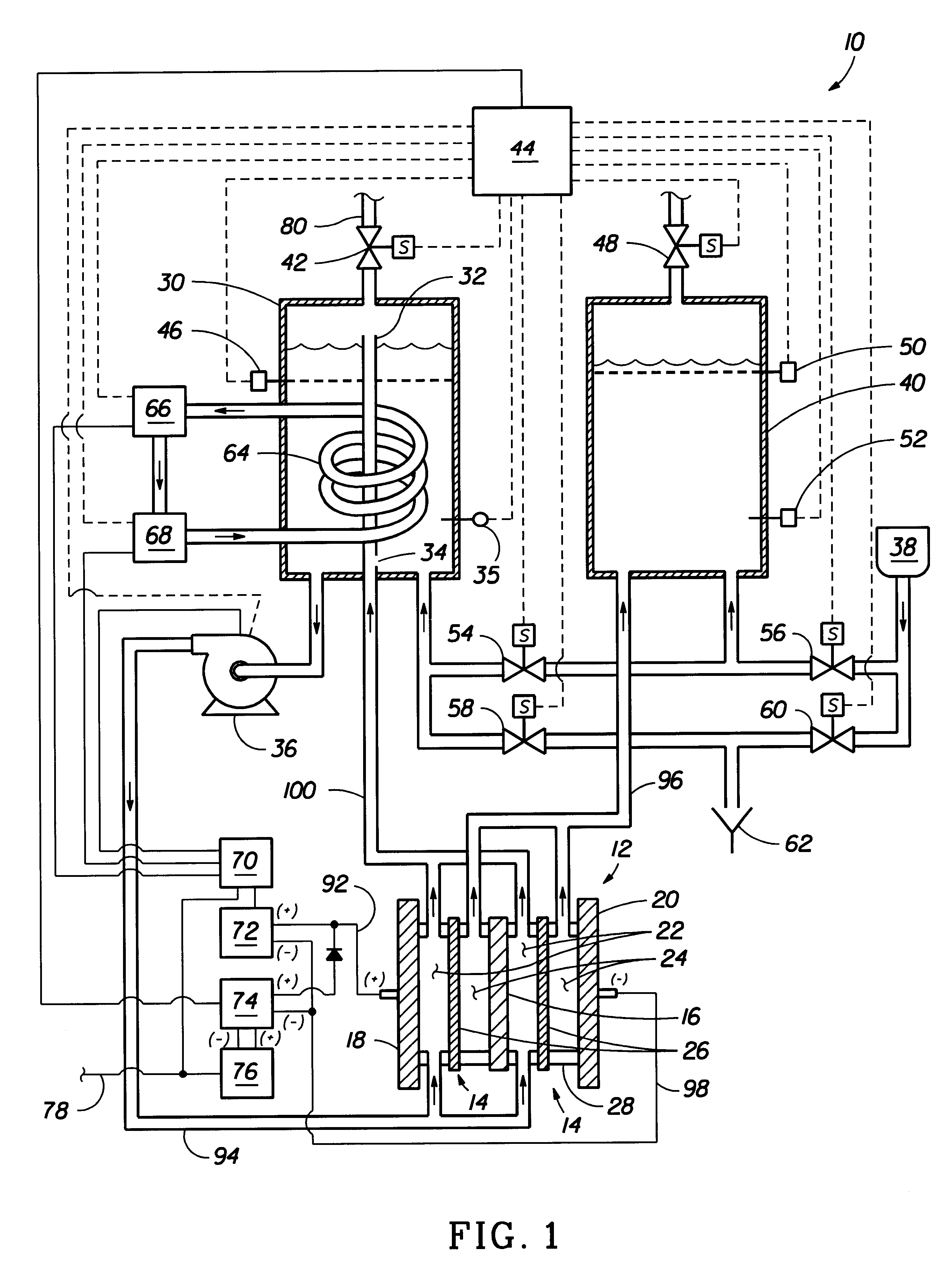
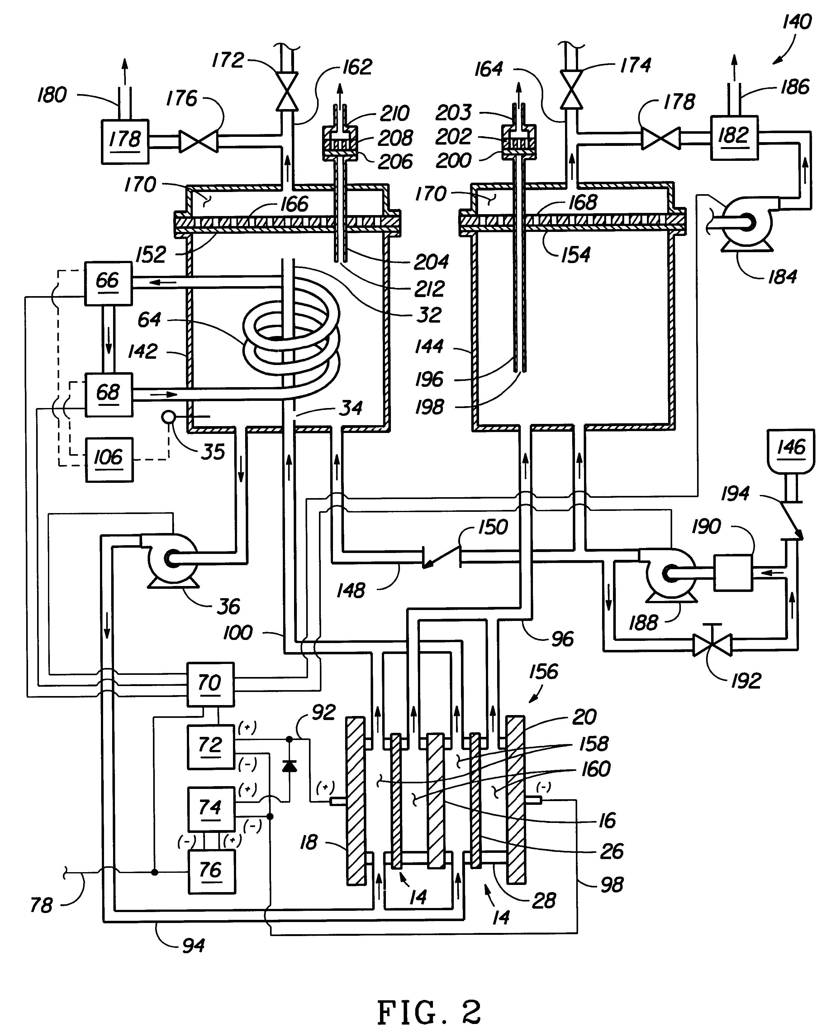
An ozone generator was designed in accordance with FIGS. 1, 3 and 4 to produce about 5 pounds per day of ozone from about 5 gallons per day of deionized water. A stack of 10 electrolytic cells were used to generate a continuous output of about 7 liters / minute of a wet oxygen stream having about 15 wt % of ozone. Each cell had an active area of about 100 square centimeters. The anode flowfield was provided by three rolled, expanded sheets of titanium and a layer of sintered titanium in electrical contact with the expanded titanium. The sintered titanium layer had a thin layer of a lead dioxide catalyst deposited onto its surface and the lead dioxide was placed in face-to-face contact with a proton exchange membrane (PEM). The PEM was a sheet of perfluorinated sulfonic acid polymer, NAFION 117. The cathodic electrocatalyst was provided by a carbon fiber paper impregnated with a platinum catalyst. The fiber paper was placed against the second side of the PEM. The cathode flowfield was ...


PUM

PropertyMeasurementUnit
current efficiencyaaaaaaaaaa
temperaturesaaaaaaaaaa
pressureaaaaaaaaaa

Abstract

An ozone generator which operates at constant pressures to produce a continuous flow of ozone in an oxygen stream having from 10% to 18% by weight of ozone. The ozone generator includes one or more electrolytic cells comprising an anode / anode flowfield, a cathode / cathode flowfield, and a proton exchange medium for maintaining the separation of ozone and oxygen from hydrogen. The ozone generator also has an anode reservoir which vents oxygen and ozone and a cathode reservoir which vents hydrogen. The anode reservoir can be filled from the cathode reservoir while continuing to produce ozone. The ozone generator is readily configured for self-control using a system controller programmed to operate the anode reservoir at a constant pressure.

Description

1. Field of the inventionThis invention relates to the production of ozone for use in a variety of processes such as decontamination of water. More specifically, the invention relates to an electrochemical cell and a process for generating ozone in the electrochemical cell.2. Background of the Related ArtOzone has long been recognized as a useful chemical commodity valued particularly for its outstanding oxidative activity. Because of this activity, it finds wide application in disinfection processes. In fact, it kills bacteria more rapidly than chlorine, it decomposes organic molecules, and removes coloration in aqueous systems. Ozonation removes cyanides, phenols, iron, manganese, and detergents. It controls slime formation in aqueous systems, yet maintains a high oxygen content in the system. Unlike chlorination, which may leave undesirable chlorinated organic residues in organic containing systems, ozonation leaves fewer potentially harmfull residues. Ozone has also been shown t...

Claims


Application Information

Patent Timeline
Patent Type & Authority Patents(United States)
IPC IPC(8): C01B13/10C02F1/467C02F1/461C25B1/13C25B1/00C25B9/06C25B9/10C02F1/78C25B9/23
CPCC25B1/13C25B9/10C01B13/10C02F1/4672C02F2201/4617C02F2303/18C02F1/46104C02F1/46109C02F1/78C02F2001/46128C02F2001/46142C02F2001/46157C02F2201/46115C02F2201/4612C02F2201/46155C02F2201/4616C25B9/23
Inventor ANDREWS, CRAIG C.MURPHY, OLIVER J.
Owner LYNNTECH
Why Eureka
Try Eureka