Apparatus for bonding a particle material to near theoretical density

a particle material and fast bonding technology, applied in heat treatment apparatus, furnaces, furnaces, etc., can solve the problems of limiting the final density that can be achieved, significantly affecting the consolidation process, and requiring long processing time and high chamber temperature to produce high-density parts, etc., to achieve the effect of high shear, and reducing the time and temperature required for consolidation or joining

Inactive Publication Date: 2001-10-30
MATERIALS MODIFICATION INC
View PDF2 Cites 29 Cited by
  • Summary
  • Abstract
  • Description
  • Claims
  • Application Information

AI Technical Summary

Benefits of technology

The principal object of the present invention is to provide an apparatus for rapidly bonding a particle material to near theoretical density with minimum grain growth and to join or bond with high interface integrity and minimum microstructural distortion in the bulk material.
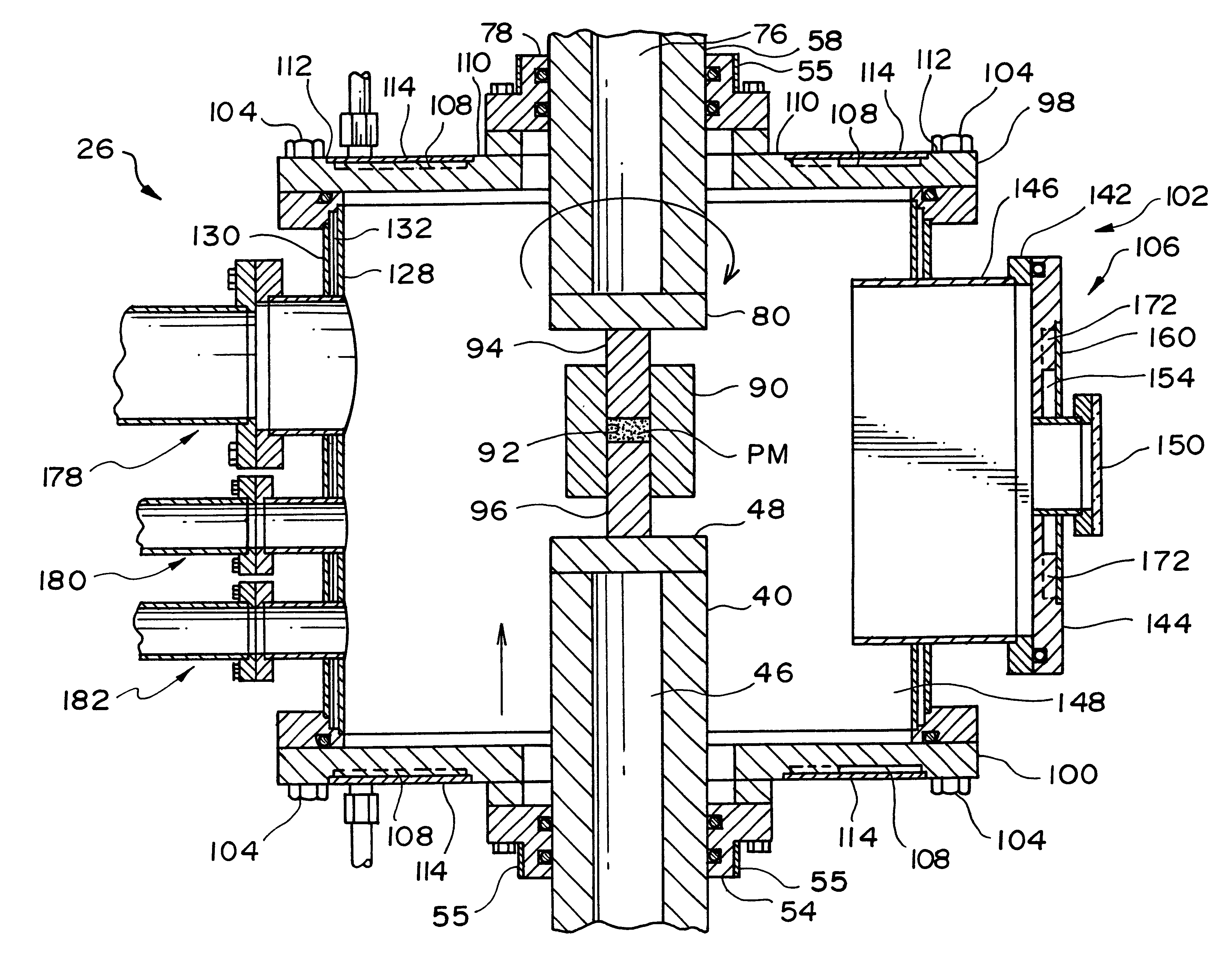
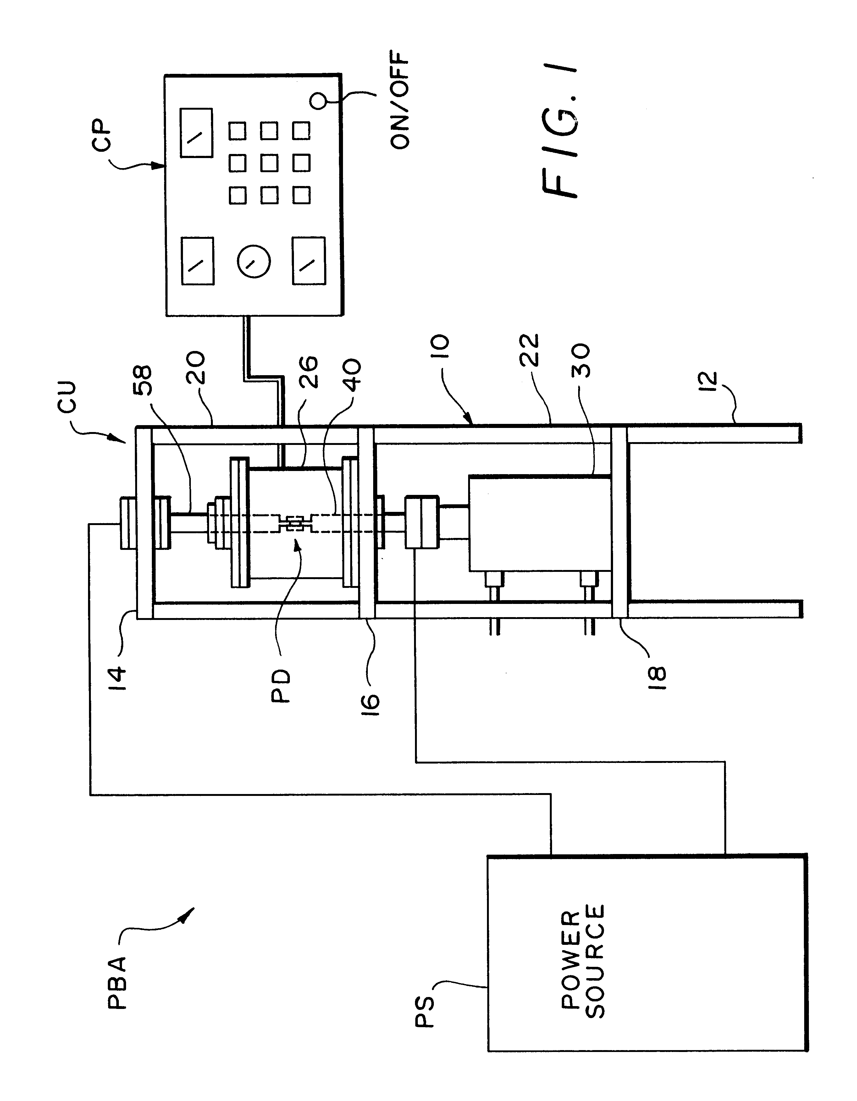
The control panel 190 includes of a series of switches which can be controlled manually or through a computer. The control panel provides the following switches--power ON, power OFF, pulsing ON, pulsing OFF, meter for reading the voltage, meter for reading the current, switch for controlling the voltage, current, pulsing rate, base line, peak current, duty cycle, ramp up time, ramp down time and forward / reverse switch. The forward / reverse switch changes the polarity of the plungers 40 and 58. This is extremely important for densifying parts with a part length of greater than one inch. Changing polarity also ensures uniform distribution of the temperature within the powder material to be bonded or densified.

Problems solved by technology

The conventional techniques require long processing time and high chamber temperature in order to produce high-density parts.
However, powder particles with large surface area, due to their surface charge distribution, readily react with the atmosphere and form a stable oxide phase, which significantly affects the consolidation process.
The presence of these oxides, moisture and other contaminants on the surface of the particles, limits the final density that can be achieved and degrades the mechanical properties of the consolidated parts.
The consolidation of powders to near theoretical density, without significant grain growth has been a difficult task because of the tendency for the grains to coarsen at elevated temperature.
However, the drawback is that the total time required for consolidation at the elevated temperature, is very long (several hours) which leads to significant grain growth, and poor mechanical and thermal properties.
However, long preparation and processing times are required in the conventional techniques that result in high manufacturing cost.
Unfortunately, wide use of these materials is limited due to high cost of fabrication.
In summary, both the conventional (hot pressing, hot-isostatic pressing, sintering) and non-conventional powder densifying equipment (ROC-Rapid Unidirectional Compaction, Electroconsolidation, Quick-Hot Isostatic Pressing) are not designed for consolidating powders rapidly to full or near-theoretical density with minimum grain growth.
The prior art apparatus are also not considered effective at least for the reasons that they: are limited to producing smaller size parts, result in nonuniform distribution of temperature throughout the powder compact, result in lower than near theoretical densities, result in undesirable grain growth, do not reactively consolidate or join the materials, do not consolidate or join precursor particle materials, require pretreatment or presynthesis of the particle material, do not apply to ultrafine particles (<1 micron), etc.

Method used


Image

  • Apparatus for bonding a particle material to near theoretical density
  • Apparatus for bonding a particle material to near theoretical density
  • Apparatus for bonding a particle material to near theoretical density

Examples


example 2

The power supply was connected to a 432-458V / 3 phase AC power supply with a maximum current of 300 amps. The power supply converted the input power into 0-10V / 0-10000 amps DC power. This current was fed to the plungers both in the forward and the reverse mode. Plasma temperatures from 20 to 2500.degree. C. were observed. Pulsing rate was varied from 10 Hz to 100 Hz. Base line was varied from 100 A to 8000 A and duty cycle was varied from 0-90%. Series of powder densification experiments were performed on metallic, ceramic, intermetallic and composite powders. Fully dense parts were obtained with minimum grain growth.

example 3

The power was connected to a 440V / 3 phase AC power supply with a maximum current of 300 amps. The power supply converted the input power into 0-10V / 0-10000 amps DC power. This current was fed to the plungers both in the forward and the reverse mode. Plasma temperatures of up to 2500.degree. C. were observed. One of the plungers was rotated at 2 to 25 revolutions per minute to apply shear force. Series of powder densification experiments were performed on metallic, ceramic, intermetallic and composite powders. Fully dense parts were obtained with minimum grain growth.

example 4

The power supply was connected to a 208-220V / 3 phase AC power supply with a maximum current of 300 amps. The rectifier converted the input power into 0-10V / 0-4000 amps DC power. This current was fed to the plungers both in the forward and the reverse mode. Plasma temperatures of up to 20 to 2500.degree. C. were observed. Hydraulic cylinder was replaced with pneumatic cylinder, which was connected to a compressed air source. Pressures of up to 70 MPa were applied using this system on graphite and carbon-carbon plungers and dies.


PUM

PropertyMeasurementUnit
axial pressureaaaaaaaaaa
particle sizesaaaaaaaaaa

Abstract

An apparatus for bonding a particle material to near theoretical density, includes a chamber, a punch and die assembly for supporting a particle material, plungers for applying shear and / or axial pressures, and a power supply for applying a current. In the first stage, a pulsed current of about 1 to 20,000 amps., is applied to the particle material for a predetermined time period, and substantially simultaneously therewith, a shear force of about 5-50 MPa is applied. In the second stage, an axial pressure of about less than 1 to 2,000 MPa is applied to the particle material for a predetermined time period, and substantially simultaneously therewith, a steady current of about 1 to 20,000 amps. is applied. The apparatus may be used to bond metallic, ceramic, intermetallic and composite materials to near-net shape, directly from precursors or elemental particle material without the need for synthesizing the material. The method may also be applied to perform combustion synthesis of a reactive material, followed by consolidation or joining to near-net shaped articles or parts. The apparatus may further be used to repair a damaged or worn substrate or part, coat a particle onto a substrate, and grow single crystals of a particle material.

Description

FIELD AND HISTORICAL BACKGROUND OF THE INVENTIONThe present invention is directed to bonding particle materials, and more particularly to an apparatus for reactive or nonreactive synthesis, consolidation, or joining of metallic, ceramic, intermetallic, or composite materials to near-net shapes by application of high shear, high current (1-20 kA), and high pressure (about 1 to 2,000 MPa).Pressure-assisted consolidation or sintering generally involves heating a particle powder compact, while applying pressure simultaneously. The powder compacts are typically heated externally using graphite or molybdenum heating elements and the pressure is applied hydraulically, pneumatically or isostatically using various types of gases depending on the type of the process. Conventional pressure assisted consolidation techniques include hot pressing, hot isostatic pressing, hot forging, and hot extrusion. The conventional techniques require long processing time and high chamber temperature in order ...

Claims


Application Information

Patent Timeline
Patent Type & Authority Patents(United States)
IPC IPC(8): B22F3/00B22F3/14C04B35/64B22F3/035B22F3/093
CPCB22F3/093B22F3/14C04B35/64B22F3/105B22F2999/00Y10S977/775Y10S977/776Y10S29/031
Inventor YOO, SANG H.SETHURAM, KRUPASHANKARA M.SUDARSHAN, TIRUMALAI S.
Owner MATERIALS MODIFICATION INC
Why Eureka
Try Eureka