Hard multilayer coated tool having increased toughness
- Summary
- Abstract
- Description
- Claims
- Application Information
AI Technical Summary
Benefits of technology
Problems solved by technology
Method used
Image
Examples
example 2
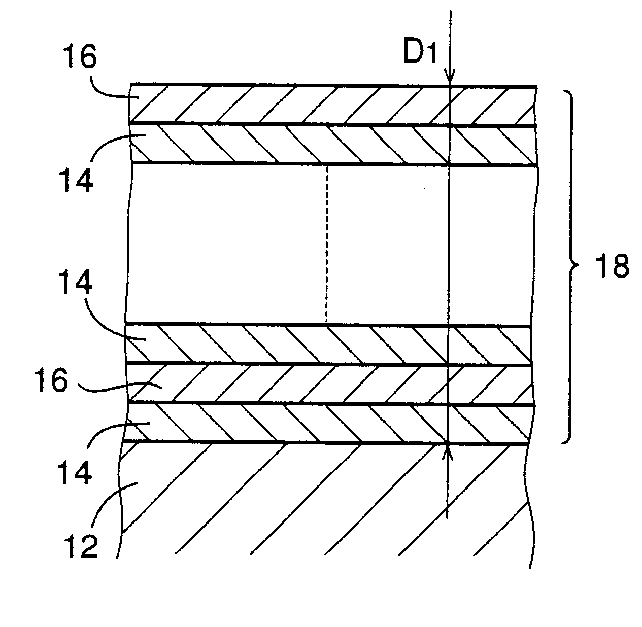
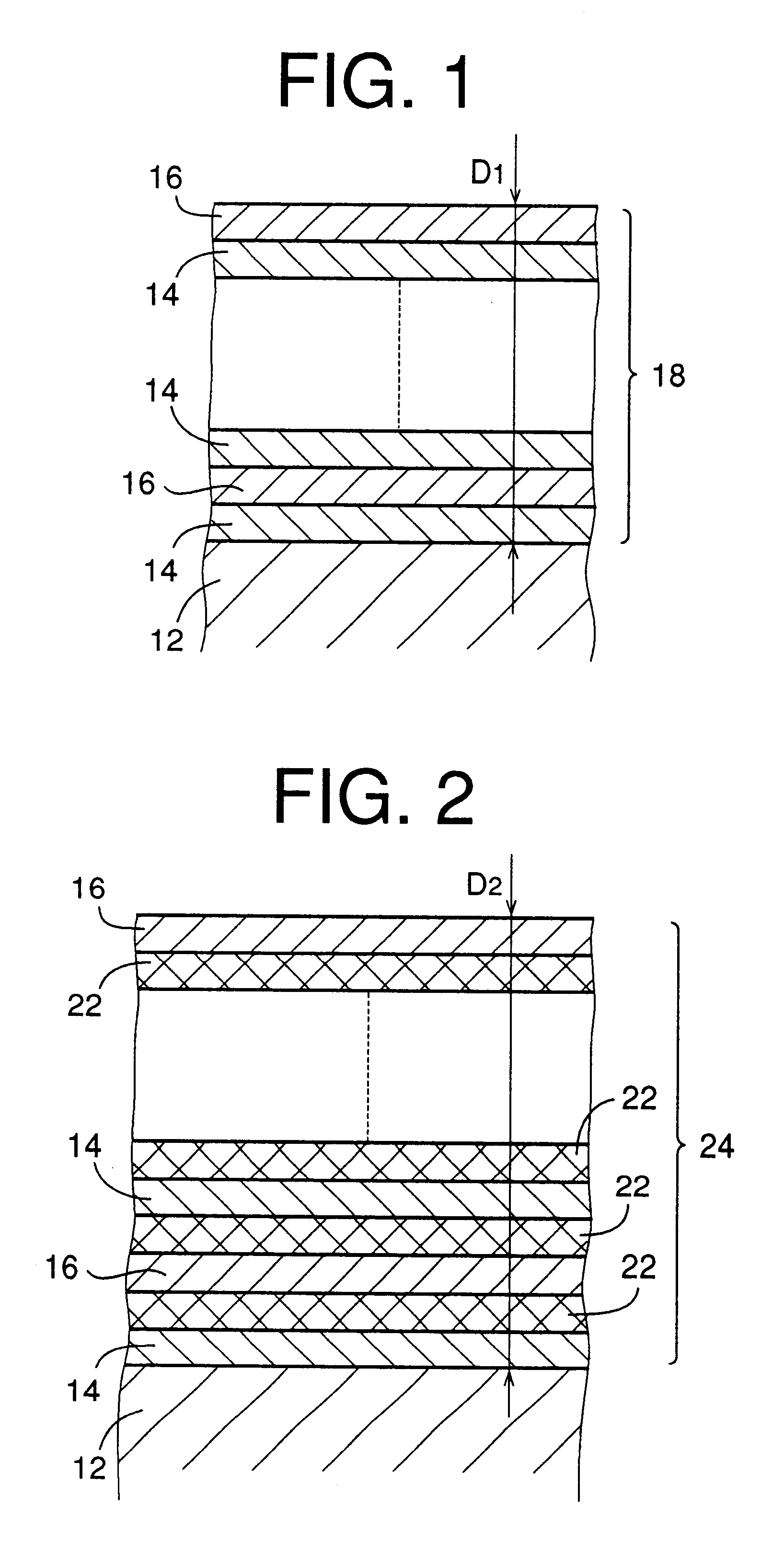
A hard multilayer coating was formed under a condition which was identical with the above-described condition of the example 1 except that Al.sub.0.4 Ti.sub.0.6 alloy was used as a target in the formation of the inner layers and that Al.sub.0.8 Ti.sub.0.2 alloy was used as a target in the formation of the outer layers. The composition of the inner layer and that of the outer layer were Al.sub.0.39 Ti.sub.0.61 N and Al.sub.0.78 Ti.sub.0.22 N, respectively. Thus, the mixing ratio of the aluminum in the entirety of the multilayer coating resulted in 0.59[.apprxeq.(0.39+0.78).div.2].
example 3
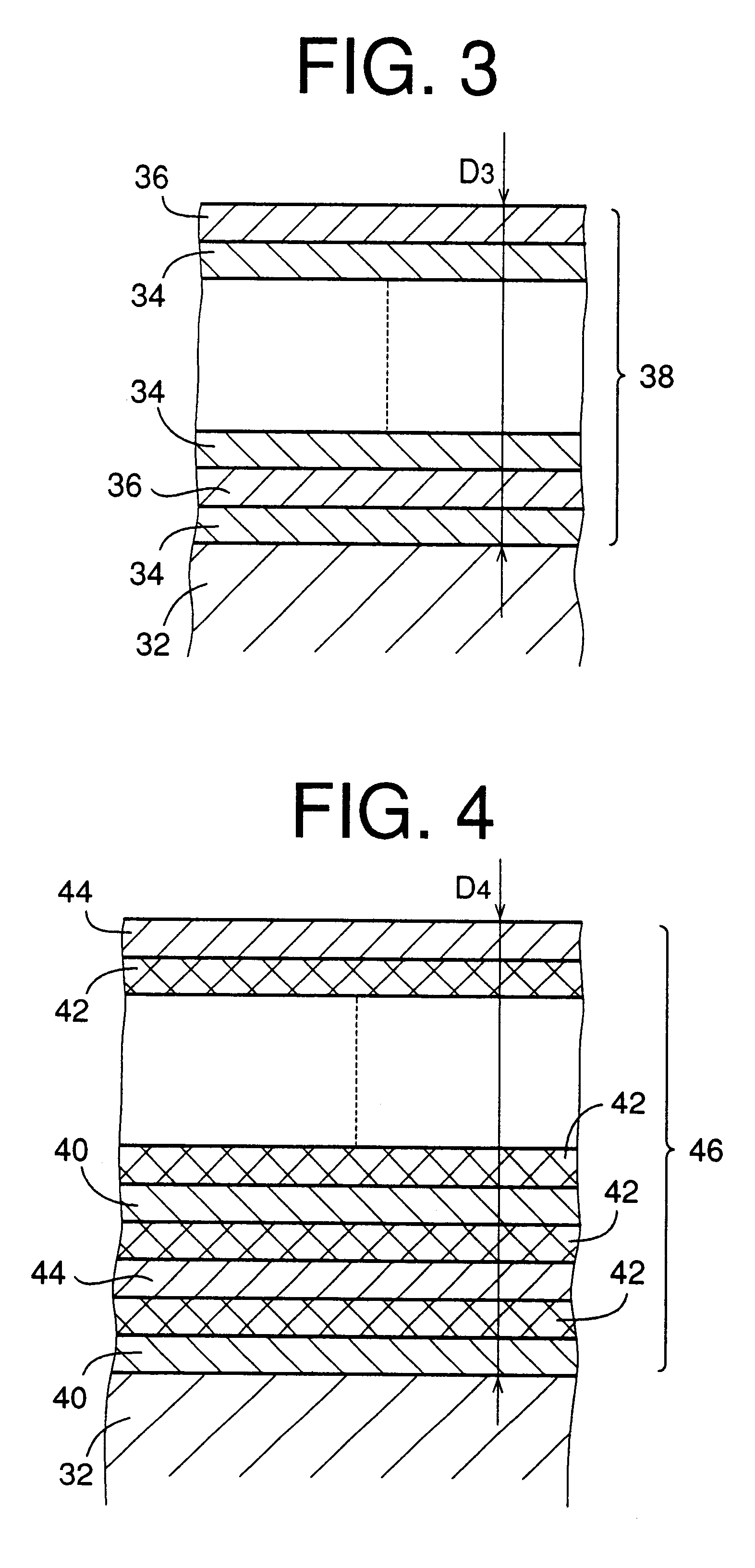
A hard multilayer coating was formed under a condition which was identical with the above-described condition of the example 1, except that Al.sub.0.3 Ti.sub.0.7 alloy and Al.sub.0.7 Ti.sub.0.3 alloy were used as targets in the formations of the inner and outer layers, respectively, and that the average thickness of the inner and outer layers were 0.10 .mu.m and 0.20 .mu.m, respectively, so that the pitch or spacing interval between each adjacent two of the outer layers or between each adjacent two of the inner layers was 0.30 .mu.m (=the thickness of 0.10 .mu.m of each inner layer+the thickness of 0.20 .mu.m of each outer layer). The composition of the inner layer and that of the outer layer were Al.sub.0.29 Ti.sub.0.71 N and Al.sub.0.68 Ti.sub.32 N, respectively. Thus, the mixing ratio of the aluminum in the entirety of the multilayer coating resulted in 0.55 [=(0.29+0.68.times.2) .div.3].
example 4
A hard multilayer coating was formed under a condition which was identical with the above-described condition of the example 1, except that Al.sub.0.3 Ti.sub.0.7 alloy and Al.sub.0.8 Ti.sub.0.2 alloy were used as targets in the formations of the inner and outer layers, respectively, and that an interface layer of TiN having a thickness of 0.10 .mu.m is formed by using Ti as a target. The interface layer is interposed between the surface of the substrate and the multilayer coating for further increasing the adhesiveness of the multilayer coating to the base material of the endmill. Further, differently from in the example 1, the average thickness of the inner and outer layers were 0.10 .mu.m and 0.20 .mu.m, respectively, so that the spacing interval between each adjacent two of the outer layers or between each adjacent two of the inner layers was 0.30 .mu.m (the thickness of 0.10 .mu.m of each inner layer+the thickness of 0.20 .mu.m of each outer layer). The thickness of the multilay...
PUM
| Property | Measurement | Unit |
|---|---|---|
| Length | aaaaa | aaaaa |
| Length | aaaaa | aaaaa |
| Length | aaaaa | aaaaa |
Abstract
Description
Claims
Application Information
 - R&D
- Intellectual Property
- Life Sciences
- Materials
- Tech Scout
- Unparalleled Data Quality
- Higher Quality Content
- 60% Fewer Hallucinations
Browse by: Latest US Patents, China's latest patents, Technical Efficacy Thesaurus, Application Domain, Technology Topic, Popular Technical Reports.
© 2025 PatSnap. All rights reserved.Legal|Privacy policy|Modern Slavery Act Transparency Statement|Sitemap|About US| Contact US: help@patsnap.com


