Filtering optical fiber having a modified photosensitivity profile

a filtering optical fiber and photosensitivity technology, applied in the direction of optical fibers with multi-layer cores/claddings, optical waveguide light guides, instruments, etc., can solve the problems of systematically favoring certain frequency components within the transmitted band, particularly troublesome phenomena, and reducing photosensitivity, so as to reduce the effect of index grating strength and reducing photosensitivity

Inactive Publication Date: 2001-11-06
II VI DELAWARE INC
View PDF17 Cites 32 Cited by
  • Summary
  • Abstract
  • Description
  • Claims
  • Application Information

AI Technical Summary

Benefits of technology

In the invention, the second problem has been solved and the rebound has been almost completely eliminated by inverting the core-to-cladding photosensitivity profile. It has been found that reducing photosensiti...

Problems solved by technology

It is known that such amplifiers unfortunately present the drawback of systematically favoring certain frequency components within the transmitted band.
This phenomenon becomes particularly troublesome when such optical amplifiers are used in wavelength division multiplex (WDM) type links, where different channels are conveyed by optical carriers at different frequencies for the purpose of increasing the overall capacity and the modularity of the system.
Given the phenomenon that takes place within the optical amplifier, such favoring of particular wavelengths would be completely unaccepted if it were not regularly compensated.
This type of Bragg grating filter thus suffers from the drawback of acting as a partial reflector of those components of the amplified signal that are concerned by the filtering.
As a result, in the amplifying section, not only does the signal reflected by the filter return and interfere, but also the signal back-scattered. by the fiber is returned into the line and degrades transmission characteristics.
The drawback presented by that technique lies in the select...

Method used


Image

  • Filtering optical fiber having a modified photosensitivity profile
  • Filtering optical fiber having a modified photosensitivity profile
  • Filtering optical fiber having a modified photosensitivity profile

Examples


Embodiment Construction

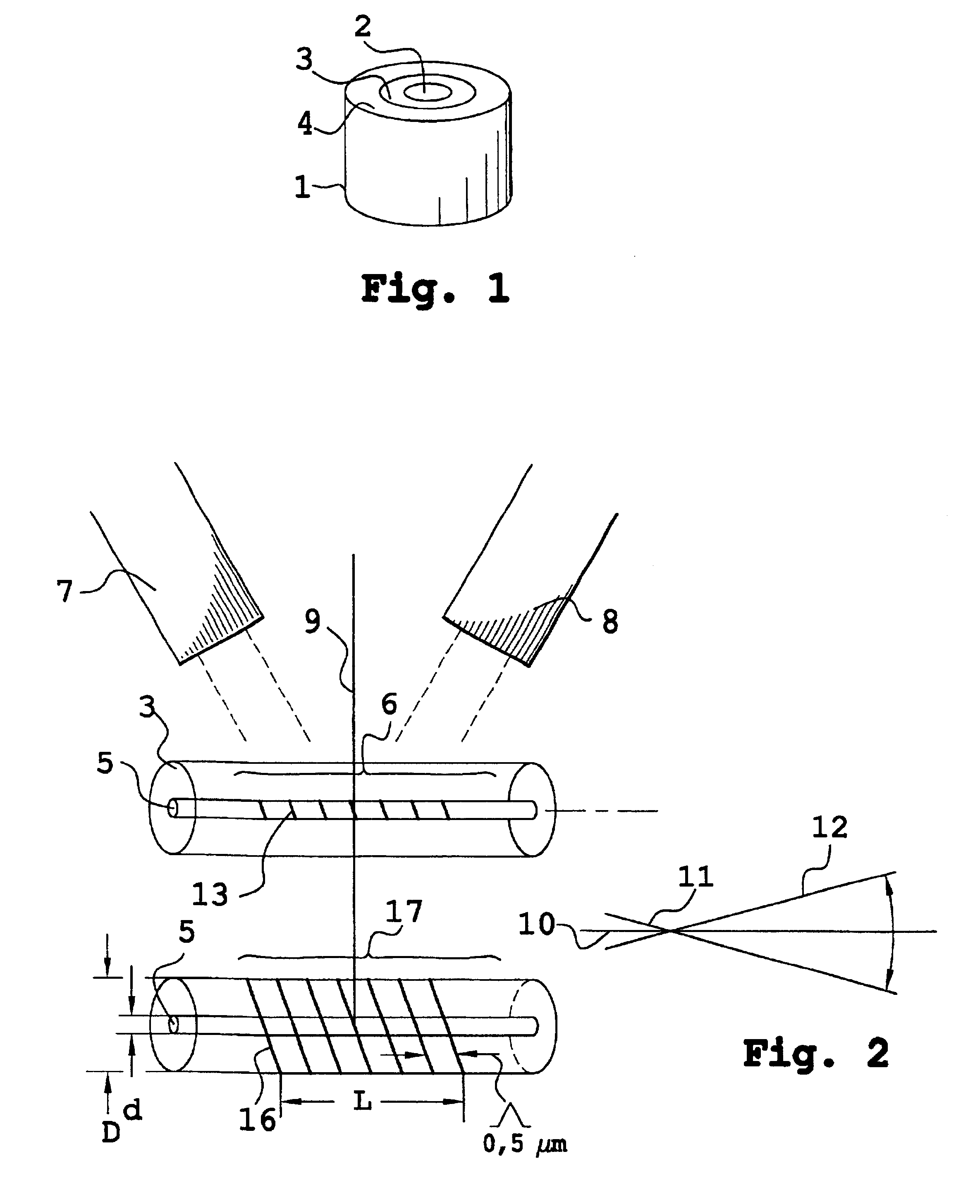
FIG. 1 shows an optical fiber preform 1. The perform 1 has a first cylinder surrounded by an inner cylindrical ring and an outer cylindrical ring 4. The cylinder and its rings represent the various layers of material present in the optical fiber after it has been made by drawing. The radial dimensions of the cylinder and cylindrical rings 2 to 4 are in the same proportions as the much smaller dimensions of the corresponding portions in the optical fiber once the fiber has been made by drawing. In practice, a fiber core and cladding corresponding respectively to layers 2 and 3 are each made up from a plurality of layers. The layers 2 to 3 are thus doped with different dopants while the preform is being built up.

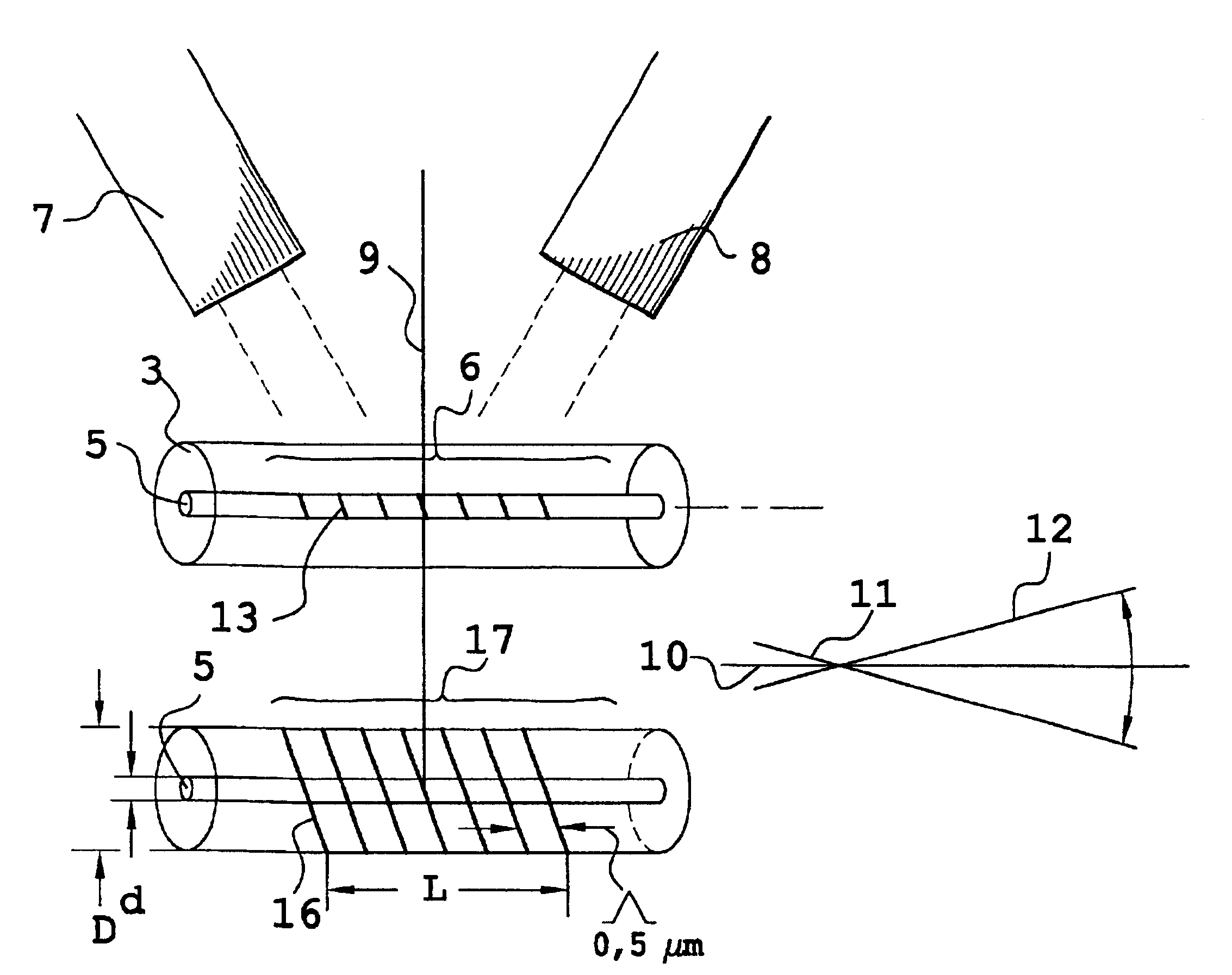
FIG. 2 shows a preferred method of exposing a photosensitive material suitable for creating a grating of index changes, also known as an index grating, within the core 5 of a fiber. In a prior art fiber, the core 5 of the fiber is doped with germanium when the cylinder 2 is ma...


PUM


Abstract

It is shown that by modifying the photosensitivity profile it is possible to provide better adjustment of the characteristic curve of a filter, and in particular to eliminate a reflection peak that is present within the working band. The photosensitivity profile is inverted to a considerable extent. In practice, the core of the fiber has only 20% of photosensitive doping material compared with the quantity of photosensitive doping material present in the cladding of the fiber.

Description

The present invention relates to a frequency filter for modifying the transmission spectrum of an optical fiber. In the invention, the frequency filter is made in a portion of optical fiber that is modified to impart filtering ability thereto.In the field of optical fiber filters, it is known to make Bragg gratings in core sections of such optical fibers. Bragg gratings are made by periodically changing refractive index in the fiber material. Such changes are obtained by irradiating said sections of the fiber core with ultraviolet radiation. The change in refractive index caused by exposure to light is know as the "photo-refractive effect". This effect is permanent. The property of a material having an index capable of being modified under such light irradiation is referred to herein as "photosensitivity". In present technology, photosensitivity characteristics are related to a defect in germanium present in the silica matrix of the optical fiber. Other dopants making the core of th...

Claims


Application Information

Patent Timeline
IPC IPC(8): G02B6/34G02B6/00G02B6/02G02B6/036
CPCG02B6/02119
Inventor RIANT, ISABELLESANSONETTI, PIERRE
Owner II VI DELAWARE INC
Why Eureka
Try Eureka