Adhesively bonded joints in carbon fibre composite structures

a carbon fibre composite and adhesive bonding technology, applied in the installation of lighting conductors, aircraft indicators, domestic objects, etc., can solve the problems of increasing potential differences across the ply structure, no readily available electrically conductive path for discharging current, and being particularly vulnerable to damag

Inactive Publication Date: 2001-11-20
BAE SYSTEMS PLC
View PDF15 Cites 87 Cited by
  • Summary
  • Abstract
  • Description
  • Claims
  • Application Information

AI Technical Summary

Problems solved by technology

In a carbon fibre composite structure, the carbon fibre plies act as very high resistance conductors and the resin in the composite acts as a highly capacitive dielectric so that lightning striking carbon fibre composite results in an increasing potential difference across the ply structure but no readily available electrically conductive path for discharging the current.
The current therefore tends to concentrate at the structural joints making them particularly vulnerable to damage.
The use of adhesives in these joints can lead to failure when lightning strikes the airframe because known adhesives have very poor conductivity and cannot safely transfer lightning current.
If the stresses exceed the joint's dielectric strength, the

Method used


Image

  • Adhesively bonded joints in carbon fibre composite structures
  • Adhesively bonded joints in carbon fibre composite structures

Examples


Embodiment Construction

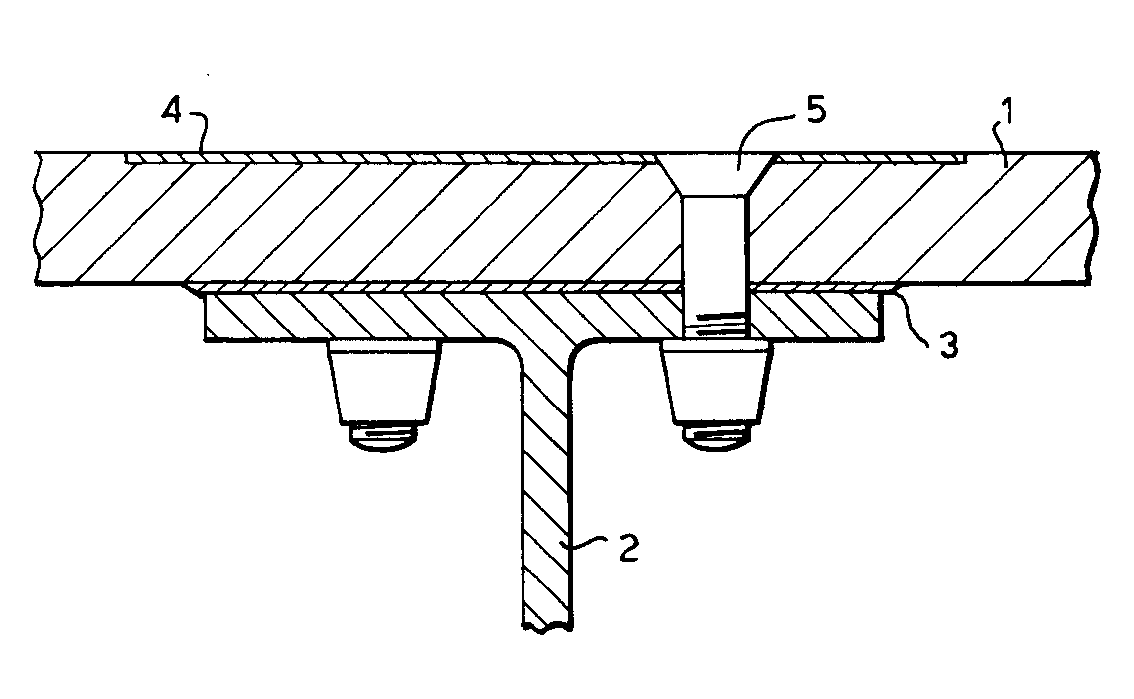
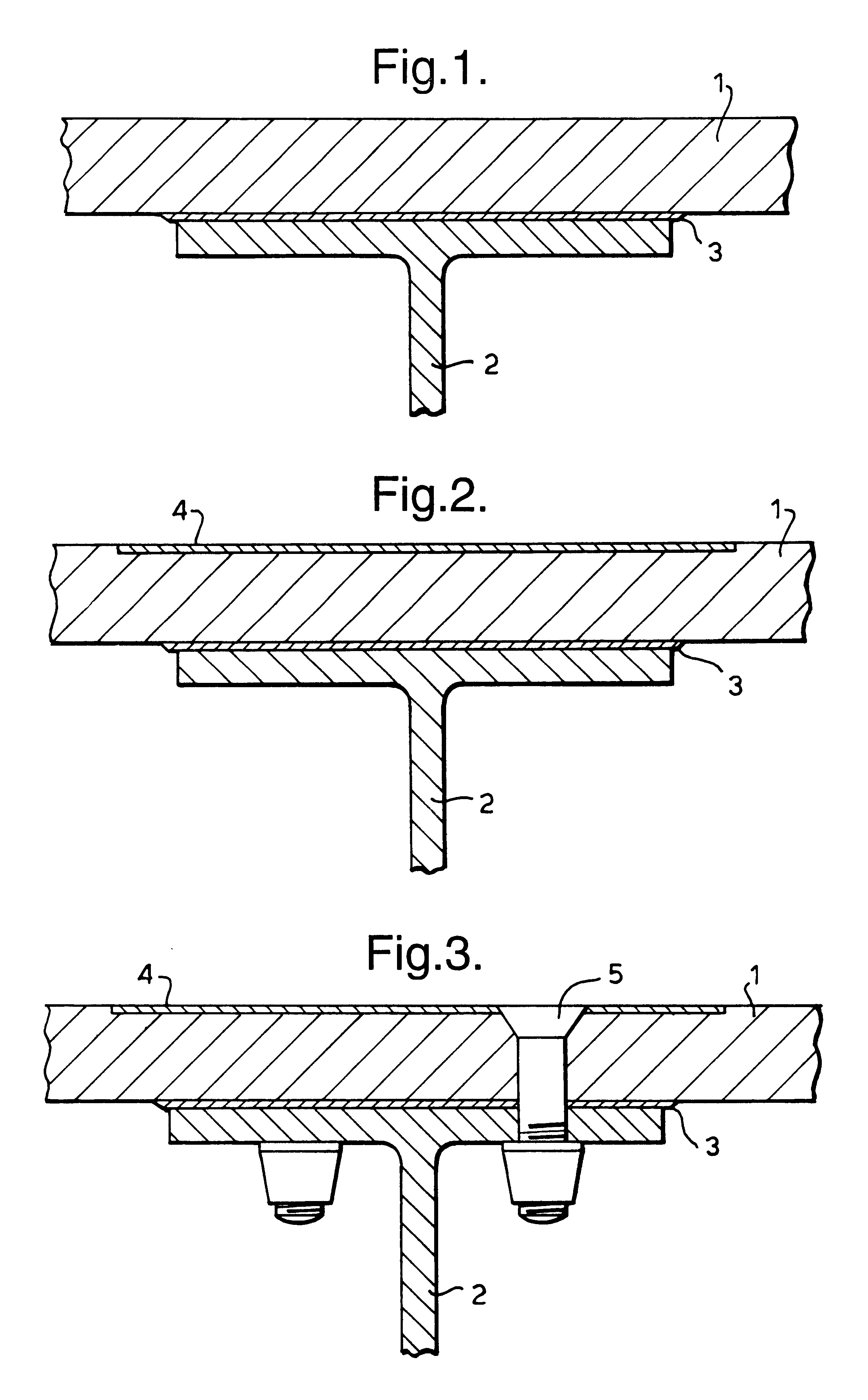
Referring to FIG. 1, a structural adhesive 3 is shown securing a skin panel 1 of an aircraft structure to an inner substructure 2 comprising the wall of a fuel tank. Both the skin panel 1 and the substructure 2 are made of carbon fibre composite material of low weight and high strength, having a percentage of 50-60% carbon fibre in the composite material. The adhesive 3 is a film adhesive containing a conductive carbon fibre carrier film, where the carbon fibres may typically be in the form of a lightweight scrim or chopped fibres. The adhesive 3 has an electrical conductivity comparable to that of the composites 1 and 2. Ideally, the percentage of carbon fibre in the adhesive 3 is typically 10-25%, and the adhesive 3 comprises little or no metallic fillers.

An alternative to the above structural arrangement is shown in FIG. 2, in which reference numerals identical to those used in FIG. 1 have been employed to indicate similar parts. Only the differences will be described.

In the join...


PUM

PropertyMeasurementUnit
Electrical conductivityaaaaaaaaaa
Currentaaaaaaaaaa
Transmissionaaaaaaaaaa

Abstract

A structural joint for the transmission and control of high current flows in a carbon fiber or carbon fiber hybrid composite structure, said joint includingat least two composite structures comprising a multiplicity of resin bonded carbon fiber plies,an adhesive applied there between and capable of conducting high currentssaid adhesive comprising a conductive carrier film comprising carbon fibers,wherein the electrical conductivity of the adhesive is comparable with that of the adjacent composite structures.

Description

1. Field of the InventionThis invention relates to adhesively bonded joints in carbon fibre composite structures or hybrids thereof.Carbon fibre composites or hybrids thereof comprising one or more laminates or plies are being used increasingly for aircraft structures in place of the aluminum or metallic compounds formerly used. Although carbon fibre composite structures are generally stronger and stiffer than their metallic counterparts, nevertheless they lack the lightning strike tolerance of the metallic components.2. Discussion of Prior ArtA lightning strike to an aircraft causes a high electric current, which may typically be of the order of a hundred thousand amps, to flow through the aircraft frame. In a carbon fibre composite structure, the carbon fibre plies act as very high resistance conductors and the resin in the composite acts as a highly capacitive dielectric so that lightning striking carbon fibre composite results in an increasing potential difference across the ply...

Claims


Application Information

Patent Timeline
IPC IPC(8): B29C65/48B64C1/00B64C1/12B64D45/00B64D45/02B29C65/52C09J9/02
CPCB29C65/4855B29C66/524B64C1/12B64D45/02B29C66/112B29C66/131B29C66/7212B29C65/488B29C66/474B29C65/4885B29K2105/06B29K2307/00B29C65/483B29C66/43441B29K2307/04B29C66/72143B29C65/562B29L2031/7172
Inventor PRIDHAM, BARRY JDUFFY, ROGER PJONES, CHRISTOPHER C. R.
Owner BAE SYSTEMS PLC
Why Eureka
Try Eureka