Non-glare film, polarizing device and display device

a polarizing device and non-glare technology, applied in the field of nonglare film, can solve the problems of poor image sharpness, high haze value of the surface of a reflection-type liquid crystal display device, and poor image sharpness of the imag

Inactive Publication Date: 2002-02-05
DAI NIPPON PRINTING CO LTD
View PDF5 Cites 137 Cited by
  • Summary
  • Abstract
  • Description
  • Claims
  • Application Information

AI Technical Summary

Benefits of technology

The present invention is based on the knowledge that in case of forming a non-glare film by laminating a non-glare layer composed of a light transmissive resin containing a light transmissive diffusing material having a refractive index different from the light transmissive resin, when the surface haze value to of the rugged surface of the non-glare layer meets "7<hs<30" and the internal haze value hi by internal diffusion of said non-glare layer meets "1<hi<15", it is possible to make small the particle diameter of the light transmissive diffusing material and make better the display quality of, for example, a liquid crystal display and the like.

Problems solved by technology

Any type of conventional non-glare films as described above obtains a light diffusing and glare preventing action by action of the surface shape of a non-glare layer and in order to enhance its glare preventing ability it is necessary to enlarge said rugged shape, but there is a problem that enlarging the ruggedness raises the haze value of a coating film and this causes deterioration in sharpness of an image.
In order to obtain a sufficient light diffusion effect from an internal scattering effect of a light diffusion film used here, the diameter of particles used needs to be made large, and doing so causes a problem that an area having a high haze value of the surface of a reflection-type liquid crystal display device is very poor in sharpness of an image.
And in case of using such a non-glare film obtaining a light diffusion effect by an internal scattering effect as said light diffusion film on the surface of a display, there is also a problem that it is not possible to prevent an external light from being reflected in the surface of the display due to a fact that the surface of it is almost flat.
Furthermore, a non-glare film of a conventional type as described above has a problem that the visibility of a display screen is degraded due to occurrence of glittering called face-glare (scintillation) on the surface of a, film.
A haze value is used as one of criteria for evaluating such a non-glare film, and there is a problem that lowering the haze value of a surface makes glare feeling called face-glare stronger and raising the haze value to solve this makes an image whitish as a whole and lowers it in black density and thereby degrades the image in contrast.
On the other hand, when lowering the haze value to remove the whitishness, a problem happens that what is called reflecting-in and glare feeling result in increasing.
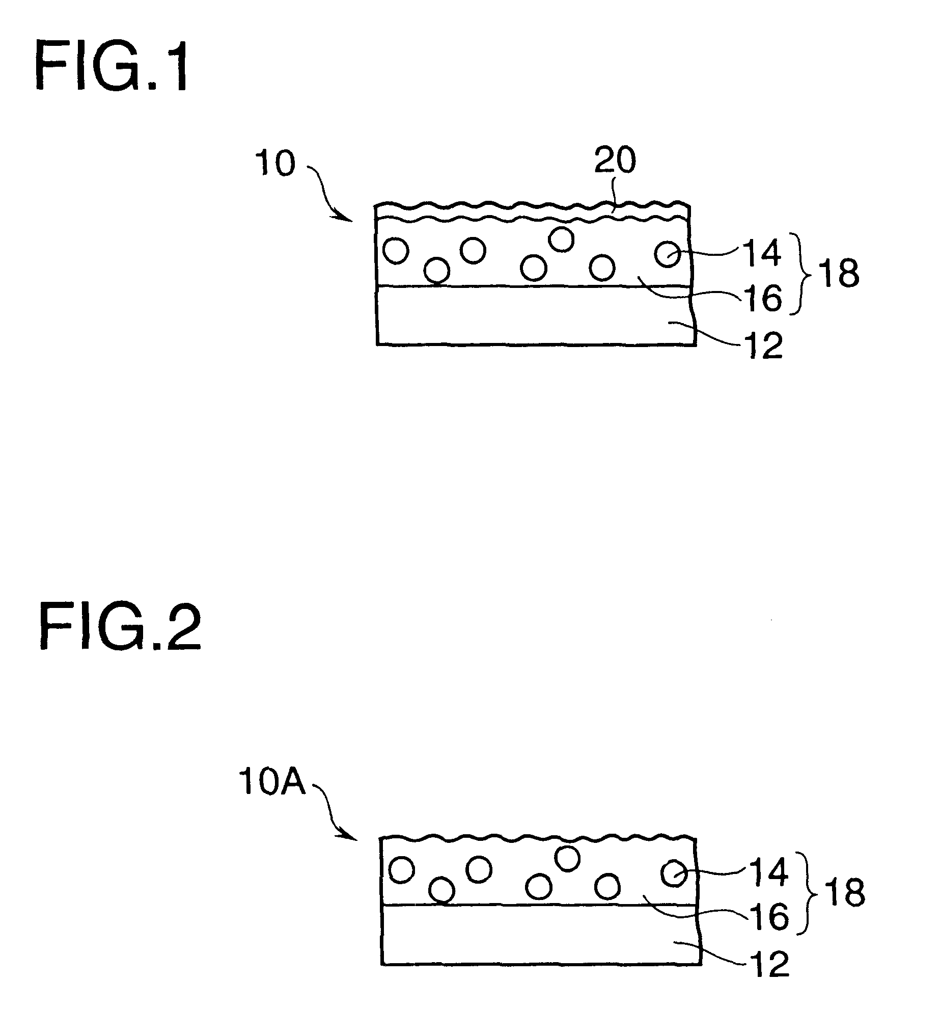
Additionally, since the non-glare layer 18 becomes thicker in film thickness, a hardening shrinkage of the light transmissive resin 16 in a manufacturing process is increased and causes crack or curl.
The more inorganic filler is added, the more effective it is in order to prevent sedimentation of the organic filler but the worse influence is given to the transparency of the coating.
When this ratio of the polymeric compound used is too small, a thin film formed by the obtained coating material comes to be low in adhesion to a base material, and on the other hand, when this ratio of it is too large, a formed film comes to be so high in refractive index as to make it difficult to provide a good antireflection effect.
A thin film formed out of a fluorine-based resin composition containing too much fluorine is liable to be low in adhesion to a base material and be slightly low in mechanical performance such as a scratch resistance and the like, and on the other hand, a thin film formed out of a fluorine-based resin composition containing too little fluorine is liable to be high in refractive index to degrade its antireflection effect.
When this amount of an initiator added exceeds 10 weight parts, this may have a bad influence on handling of the resin composition and the mechanical strength and the like of a formed thin film, and on the other hand, the amount of an initiator added being less than 0.5 weight parts makes the hardening speed small.

Method used


Image

  • Non-glare film, polarizing device and display device
  • Non-glare film, polarizing device and display device
  • Non-glare film, polarizing device and display device

Examples


embodiment 1

forms a non-glare layer similar to that of embodiment 1, applies a saponification process to it and then forms an SiO2 film of 0.1 .mu.m in film thickness as a low refractive index layer on the non-glare layer by means of a deposition process, and further provides a contamination preventing layer on it. The condition for deposition of SiO2 is that the degree of vacuum is 4.times.10.sup.5 Torr, the voltage is 8 kV and the current is 20 to 40 mA.

And the contamination preventing layer is a contamination preventing layer of about 5 nm in film thickness formed by applying a KP-801M (product name; by Shin-Etsu Chemical Co., Ltd.) which is diluted to 0.07% with a fluorine-based solvent PF5080 (product name; by 3M) to a sample and dries it at 80.degree. C. for one minute.

Each of examples 4 to 6 omits a low refractive index layer from each of embodiments 1 to 3, and therefore has no saponification process.

Next, example 7 is described.

Although not described in Table 1, a manufacturing method ...


PUM

PropertyMeasurementUnit
surface roughness Raaaaaaaaaaa
refractive indexaaaaaaaaaa
particle diameteraaaaaaaaaa

Abstract

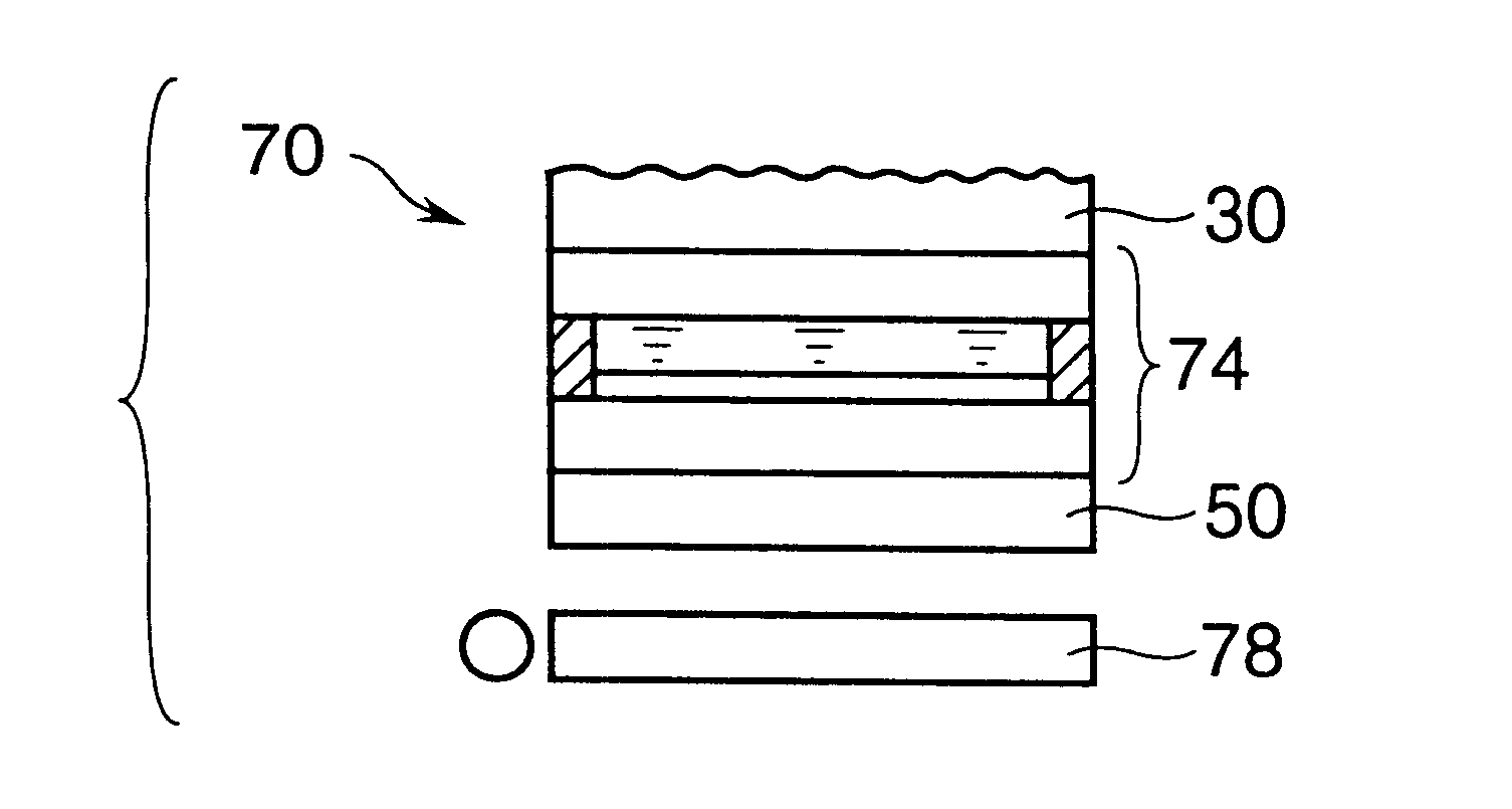
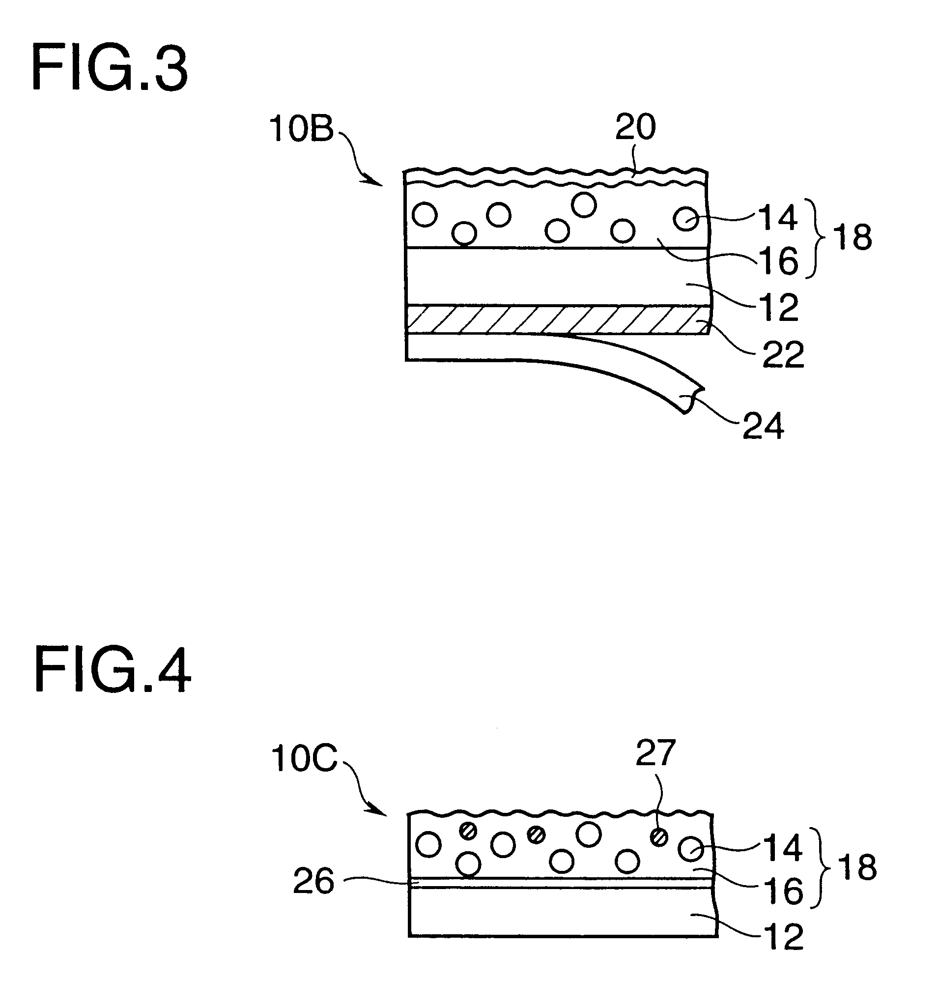
A non-glare film 10 is composed of a non-glare layer 18 formed by coating a transparent base film 12 of TAC or the like with a coating material obtained by mixing a light transmissive diffusing material 14 of resin beads and the like in a light transmissive resin 16, and a low refractive index layer 20 composed of a silicon-containing vinylidene fluoride copolymer, said low refractive index layer 20 being laminated onto the surface of the non-glare layer, in which the haze value on the surface of the non-glare layer 18 is 7 to 30 and the haze value inside the non-glare layer 18 is 1 to 15, and when the non-glare film is attached onto the surface of a display panel, it suppresses degradation in contrast and furthermore prevents face-glare, reflecting-in and whitening.

Description

1. Field of the InventionThe present invention relates to a non-glare film and a polarizing device to be preferably used on the surface of a high-resolution image display such as a cathode ray tube (CRT), a liquid crystal panel and the like to be used in an image display of a word processor, a computer, a television and the like, and a display device using the same non-glare film or polarizing device.2. Related ArtIn a display as described above, when a light emitted mainly from the inside comes straight on without diffusing on the display surface, a viewer of the display surface feels dazzling. In order to prevent this, the display surface is provided with a non-glare film for diffusing a light emitted from the inside to some degree. Such a non-glare film is formed by coating the surface of a transparent base film with a resin containing a filler such as silicon dioxide (silica) and the like, as disclosed, for example, in Japanese Patent Laid-Open Publication No. Hei 6-18706, Japan...

Claims


Application Information

Patent Timeline
Patent Type & Authority Patents(United States)
IPC IPC(8): G02B5/30G02B5/02
CPCG02B5/0242G02B5/3033G02B5/0278G02B5/0268G02B1/10
Inventor SUZUKI, HIROKO
Owner DAI NIPPON PRINTING CO LTD
Why Eureka
Try Eureka