Multiple drum mixing system

Inactive Publication Date: 2002-04-02
NIEW INDS
View PDF4 Cites 17 Cited by
  • Summary
  • Abstract
  • Description
  • Claims
  • Application Information

AI Technical Summary

Problems solved by technology

A significant problem with such systems is that the fine material carried out with the air not only causes pollution, but the fines are also lost from the mix.
Any such material that does not go into the mix is a loss, and must be replaced with further aggregate material, at added cost.
A second significant problem with conventional drum mixers is that the liquid asphalt is exposed to very

Method used


Image

  • Multiple drum mixing system
  • Multiple drum mixing system
  • Multiple drum mixing system

Examples


Embodiment Construction

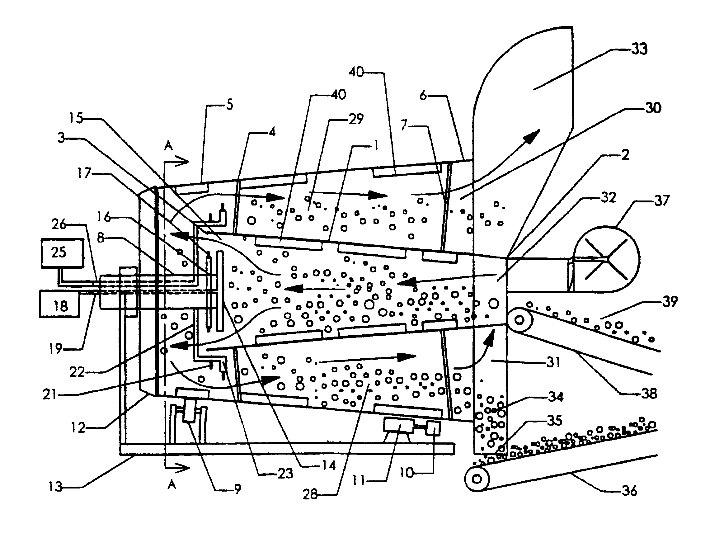
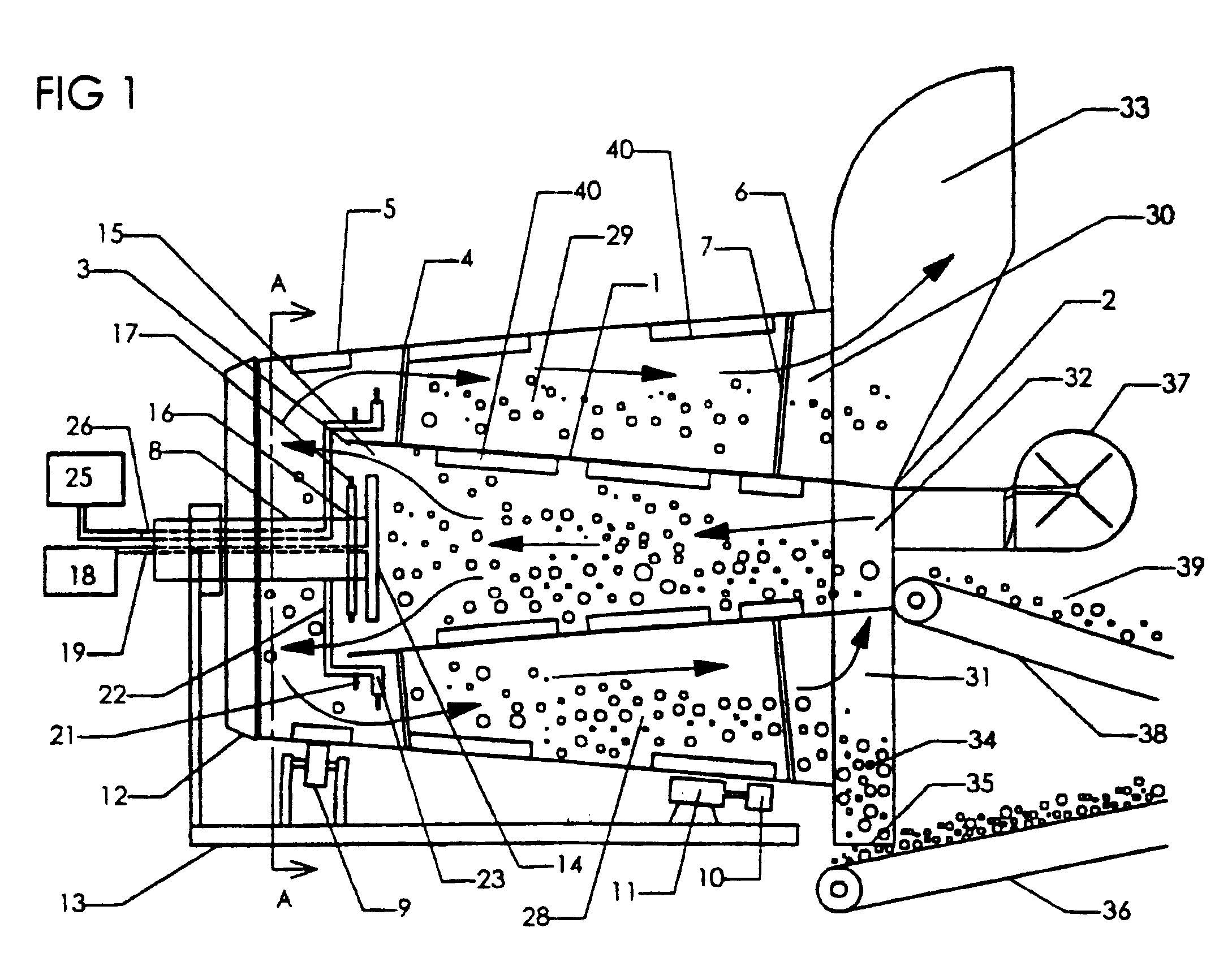
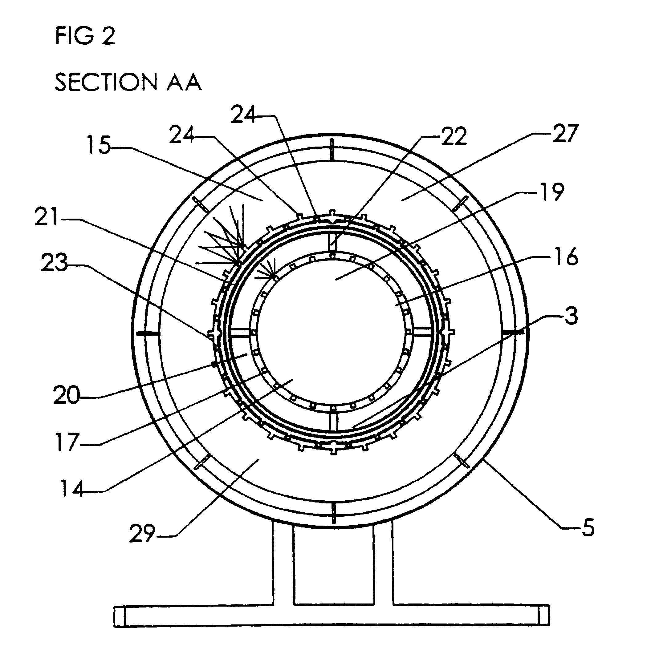
FIGS. 1 and 2 show one preferred embodiment of the invention designed for use where the material is aggregate and the additive material is liquid asphalt, providing an asphalt mixing plant.

FIG. 1 shows the inner drum 1, having an input end 2 and an output end 3, and the outer drum 4, having an input end 5 and an output end 6. The input end ends 2,5 are smaller in diameter than the output ends 3,6 of the respective drums 1,4. Outer drum shroud 12 encloses the input end 5 of the outer drum 4. The drums 1,4 are attached together by drum braces 7 to form a drum assembly which is supported on the lower frame 13 at drive wheel 10 and support wheels 9. Drive wheel 10 is rotationally driven by motor 11, and the drum assembly is thereby rotated. Disc 14 is supported on the end of the upper frame 8, partially inside the output end 3 of the inner drum 1, thus restricting that output end 3 such that all material and air must flow around the disc through an annular passage 15. Water nozzle ring ...


PUM

PropertyMeasurementUnit
Diameteraaaaaaaaaa
Additivityaaaaaaaaaa

Abstract

A drying and mixing plant is provided comprising a tapered inner drum (1) and an oppositely tapered outer drum (4) attached together concentrically and rotated as a unit. A burner (37) directs a hot air stream into the small end (2) of the inner drum (1). Material is fed into the small end of the inner drum, where impellers (40) lift it and drop it into the hot air stream and move the material through the inner drum (1) aided by the downward taper of the inner drum. The material exits the inner drum and enters the outer drum (4) where an additive material is introduced and mixed with the material (42) as both move through the chamber (28) between the inner and outer drums to a material outlet. The receiving end (5) of the outer drum (4) is enclosed in a shroud (12), therefore the air stream is directed through the chamber (28) between the drums, the chamber having an expanding cross section which slows the air down allowing fines to precipitate out. The device may include nozzles (17) for spraying water across the path of the air stream and material flow, and further may include, for fluid additive materials, additive nozzles (21, 23) spraying the additive material across the path of the air and material. A third drum (43) may be provided inside the inner drum (1), allowing separate addition of a third material (47), and further reducing fines in the air. The device is particularly suitable for mixing asphalt paving mix.

Description

This application is a national stage application, according to Chapter I of the Patent Cooperation Treaty. This application claims the priority date of Mar. 10, 1998 of Canadian Patent Application No. 2,231,693 and Jul. 10, 1998 of Canadian Patent Application No. 2,243,132.This invention deals with the field of mixing plants and in particular such a plant that employs an inner and an outer drum rotating together.BACKGROUND TO THE INVENTIONVarious situations arise in industry where a material is dried and then mixed with another material. One example is where aggregate is dried and then mixed with cement for bagging as concrete mix. Another is where aggregate is dried and then mixed with liquid asphalt to produce an asphalt mixture for paving roads.An asphalt plant is used to prepare the asphalt mix. Conventionally such plants comprise a is rotating drum set up at an angle to the horizontal. A burner and fan are located adjacent to the high end directing a flow of hot air into the hi...

Claims


Application Information

Patent Timeline
IPC IPC(8): E01C19/10E01C19/02
CPCE01C19/1031E01C19/1036E01C19/1068E01C2019/1086E01C2019/1095
Inventor NIEMI, WALTER
Owner NIEW INDS
Why Eureka
Try Eureka