Cleaning device for welding wire and method of cleaning welding wire

a cleaning device and wire technology, applied in the direction of heat treatment equipment, soldering equipment, furnaces, etc., can solve the problems of contaminated outer surface of wire, high cost, complicated and expensive techniques, etc., and achieve the effect of removing surface impurities

Inactive Publication Date: 2002-04-02
LINCOLN GLOBAL INC
View PDF10 Cites 24 Cited by
  • Summary
  • Abstract
  • Description
  • Claims
  • Application Information

AI Technical Summary

Benefits of technology

In accordance with the present invention, there is provided a wire cleaner for removing impurities from the surface of elongated welding wire, preferably a cored wire, as the wire travels along a given path. This welding wire cleaning device comprises a tunnel with a tube having a central passage surrounding the path and defining a gap between the tube and the wire moving through the tube. A power supply such as a Resonant Arc Starter by The Lincoln Electric Company is provided with first and second output terminals across which is generated an AC output current. In accordance with the invention, the current has a frequency in the range of 100-300 kHz with a magnitude of at least about 1.0 amperes. By using this power supply, the heating effect is concentrated on the outer skin of the wire. The heating of the sheath penetrates to a reference depth that is quite shallow. In the novel cleaner, a first connecter attaches the first output terminal of a power supply to the tube and the second terminal of the power supply to the moving wire by a sliding contact. Thus, the high frequency current passes through the wire along the surface of the sheath between the contact and the location of the arc in the plasma gap between the tunnel and the welding wire. This plasma arc moves along the surface and, from time to time, the polarity changes. Consequently, heating is primarily by current passing through the outer skin of the sheath. A high temperature plasma is created in the wire surrounding the gap by the arc across the gap. This plasma gap is in the general range of 0.025-0.030. Since the gap is quite small, heating is by resistance heating as current passes along the wire to the point of arcing and by conduction from the hot gases created by the arc in the small gap. In this manner, a current proportional to the output current of the power supply flows along the surface of the sheath and across the gap to heat the wire as the wire moves through the tube. This heating procedure has proved successful in removing surface impurities caused by the drawing operation or caused by leakage of core material to the exterior of a wire.

Problems solved by technology

In making solid welding wire, the outer surface of the wire also becomes contaminated with certain impurities, such as drawing compound.
This technique is quite complicated and expensive.
It results in surface areas that are not clean.
Such technique is inconsistent and is not easily incorporated into a wire manufacturing facility.
Where the welding wire has been cleaned subsequent to drawing, there has been inconsistent results.
In addition, cleaning was expensive, slow, and required complex equipment.

Method used


Image

  • Cleaning device for welding wire and method of cleaning welding wire
  • Cleaning device for welding wire and method of cleaning welding wire
  • Cleaning device for welding wire and method of cleaning welding wire

Examples


Embodiment Construction

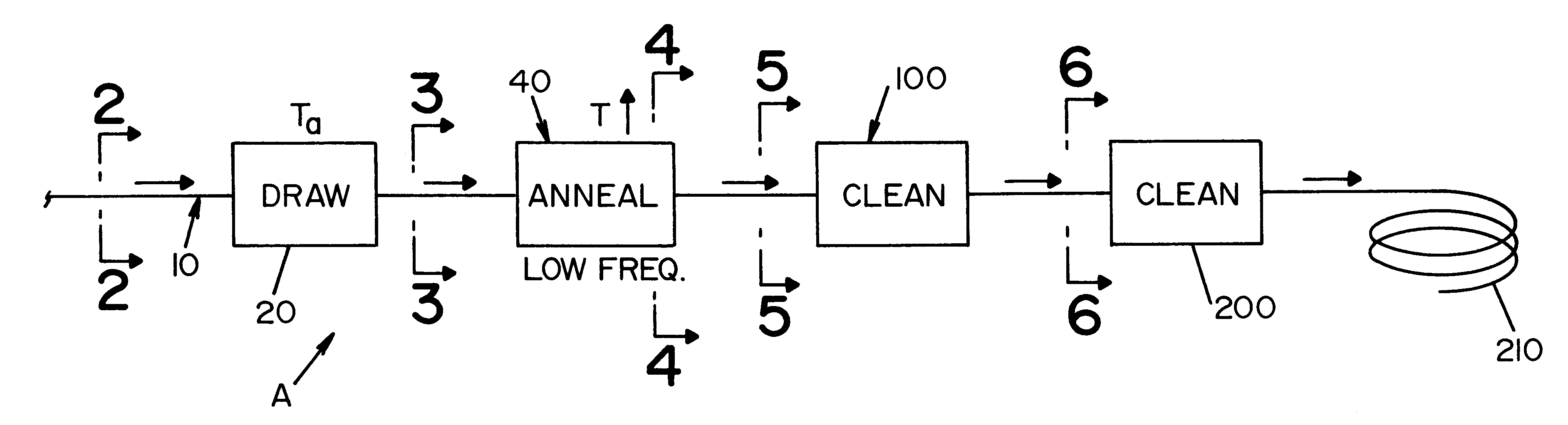
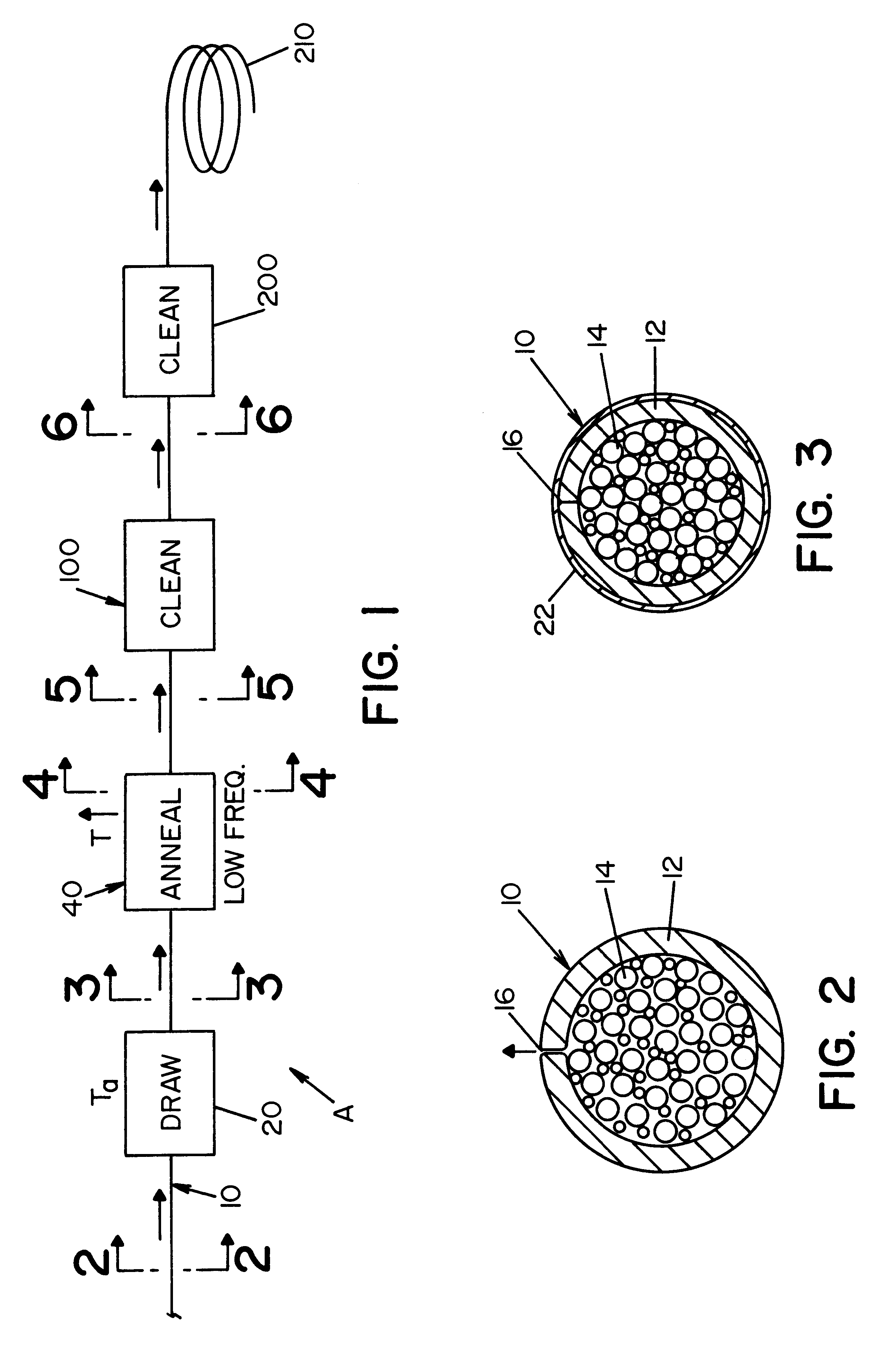
Referring now to the drawings, wherein the showings are for the purpose of illustrating a preferred embodiment of the invention only and not for the purpose of limiting the same, FIG. 1 schematically illustrates a welding wire manufacturing line A for manufacturing a welding wire 10 having an outer sheath 12 and an inner core 14 filled with particles, such as flux and alloy particles, together with a small amount of entrapped gases. The processing of wire 10 includes formation of a surface joint 16, which is illustrated as a butt joint; however, in practice it is normally an overlap joint. Wire 10 as illustrated in FIG. 2 is formed in accordance with standard practice with a small amount of impurities protruding from joint 16. As the wire moves along the manufacturing line, it moves through drawing die 20 where the wire is drawn to the desired size. Two or more drawing dies may be needed to reduce the incoming welding wire to the desired final size. This drawing operation elevates t...


PUM

PropertyMeasurementUnit
AC frequencyaaaaaaaaaa
frequencyaaaaaaaaaa
frequencyaaaaaaaaaa

Abstract

A wire cleaner for removing impurities from the surface of an elongated welding wire as the wire travels along a given path, the wire cleaner comprises a tunnel with a tube having a central passage surrounding the path with a gap between the tube and the wire moving through the tube, a power supply with first and second output terminals across which is generated an AC output current having a frequency in the range of about 100-300 kHz and a magnitude of at least about 1.0 amperes, a first connector attaching the first output terminal to the tube and a second terminal attaching the second output terminal to the moving wire whereby current proportional to the output current flows along the surface and across the gap to heat the wire to cause evaporation of the surface impurities. As an alternative, induction heating of the wire is used.

Description

This application relates to the art of manufacturing electric arc welding wire and more particularly to a cleaning device for cleaning the wire after it has been drawn to the desired size.In making solid welding wire, the outer surface of the wire also becomes contaminated with certain impurities, such as drawing compound. It has been suggested that solid wire can be cleaned by cathode cleaning using a magnetic field to rotate the arc as the electrode is progressing through a chamber or tunnel. This technique is quite complicated and expensive. It results in surface areas that are not clean. The arc is created by a voltage of 2-20 volts in a chamber filled with an inert atmosphere. A cathodic cleaning device for solid electrode wire is disclosed is Gordon U.S. Pat. No. 5,981,904. This patent is incorporated by reference herein as background information.The present invention relates to cleaning the surface of a drawn cored electrode or welding wire, and it will be described with refe...

Claims


Application Information

Patent Timeline
Patent Type & Authority Patents(United States)
IPC IPC(8): B08B7/00B23K35/00B23K35/40C23G5/00
CPCB08B7/0071C23G5/00B23K35/406B23K35/40
Inventor STAVA, ELLIOTT K.
Owner LINCOLN GLOBAL INC
Why Eureka
Try Eureka